
fuel pump electrical problem


Thread Starter
Senior Member
Joined: Jul 2009
Posts: 323
Likes: 0
From: NJ
Hello.
I have 1996 4.9L vin Y california. Midship tank fuel pump is not running but the sender works. Rear tank pump/sender works.
The chart does not list separate fuse, relay or ground for the pump or sender, so I assume those are working.
The pump side connector (pump wire harness) shows continuity for pump and sender wires.
The frame side connector shows no voltage (key on, selector front) for pump wires and 7.9 volts for sender. I guessed that thicker 2 wires are power for the pump.
Does this mean I should try replacing the connector plug and trace the wire?
Code reader is giving me "error" but I tried it with a cold engine. Will try reading again.
I'll try to decode the wiring diagram, but sure would appreciate lead-by-hand advice, like wire from connector plug goes where, etc, and steps to checking the wire integrity. Again, thanks in advance.

Thread Starter
Senior Member
Joined: Jul 2009
Posts: 323
Likes: 0
From: NJ
The problem started about 2 weeks ago. First just assumed the pump, and also gathering materials for brake line change as well while the tank was off. Finally something told me to check the electric, and that seems to be the problem.
I don't really know where the grounds are. Opened and checked around PCM box and nothing looks loose. Also I am guessing that grounds, relay and fuse are fine, since rear tank pump works. Diagram, I think, shows 2 pumps sharing one ground. I think both pumps also share one relay.
The code reader did not see any problem with fuel system, although I don't know if this truck senses problem like this.
Thanks for the reply, but could you tell me where the pump wires go from the plug on the frame? I never opened up the wire harness to trace anything. I guess that's what I'll have to do?
November 2011 TOTM Winner

Joined: Apr 2011
Posts: 1,460
Likes: 75
From: Dallas area
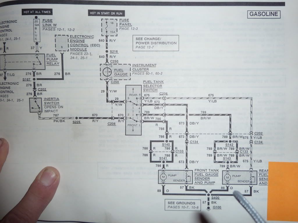
If you have no volts at the frame connector.. need to make sure your on the correct wire.. also... like Sean said, probably the switch is dropping some volts but I have a hard time believing it could drop all the volts. Could be more then one component dropping them. Best bet is to find a wire diagram and start checking volts from the tank forward. I have a print for a 90. The color codes should be the same, I will see if I can find it. Also, you are correct, the pump circuit shares a ground on the left side of the radiator.
Here it is:
Here it is:
Last edited by 5Rangers; Oct 24, 2013 at 04:05 PM.
Thread Starter
Senior Member
Joined: Jul 2009
Posts: 323
Likes: 0
From: NJ
Thank you. I took a deep breath  and took another look at the diagram. I think the trick was tracing backwards and becoming little familiar with the technical names.
It looks like the wire/connection/plug or the switch. Since rear is working, I don't think the problem goes past the selection switch.
I'll check the switch first, then consider replacing the plug. I think replacing the plug may be easier choice than opening up the wiring harness. lol.
Thanks again.
and took another look at the diagram. I think the trick was tracing backwards and becoming little familiar with the technical names.It looks like the wire/connection/plug or the switch. Since rear is working, I don't think the problem goes past the selection switch.
I'll check the switch first, then consider replacing the plug. I think replacing the plug may be easier choice than opening up the wiring harness. lol.
Thanks again.
November 2011 TOTM Winner
Joined: Apr 2011
Posts: 1,460
Likes: 75
From: Dallas area
Well, its easy enough, following the front pump circuit towards the source, 786 is the circuit code, not much there for us, but there is an R next to the wire so its a RED wire. C133 is a connector, S140 is a splice, next connector is C202, this connector also has the feed for the rear pump, so its a bigger connector. Then they go up to C205 which is another connector, the book I have gives locations, I don't have it in front of me, so Id be guessing, but I think 206 is on the inner driver wheel well and 202 is the fire wall. The switch, the relay.
You should find labels on your connectors.
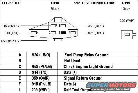
This picture doesn't show it but there's a test point to put a ground on the relay for testing purposes which this ground is normally provided by the EEC, but in your case your going to want to use the test ground to get power through your circuit to do your checks.
I'm not sure where it is on a 96, or if its even the same, mine is up by the airbox, here's a pic, looks like pin A
Anyway, when I fixed my pump circuit, I had like 7vdc at the pump, it was dropping volts all over, I was losing some at the switch, some at the firewall connector and some more at the inertia switch connector, once I got all of those working good, I have batt volts at the pump.
You should find labels on your connectors.
This picture doesn't show it but there's a test point to put a ground on the relay for testing purposes which this ground is normally provided by the EEC, but in your case your going to want to use the test ground to get power through your circuit to do your checks.
I'm not sure where it is on a 96, or if its even the same, mine is up by the airbox, here's a pic, looks like pin A
Anyway, when I fixed my pump circuit, I had like 7vdc at the pump, it was dropping volts all over, I was losing some at the switch, some at the firewall connector and some more at the inertia switch connector, once I got all of those working good, I have batt volts at the pump.
Last edited by 5Rangers; Oct 24, 2013 at 06:05 PM.
Trending Topics
Thread Starter
Senior Member
Joined: Jul 2009
Posts: 323
Likes: 0
From: NJ
Well, while I was fussing with the plugs, the connections reconnected. I think the problem is the selector switch plug. Today I tested the switch and there was continuity in both modes. Then the first time I checked the switch plug, no voltage (checking from both front blades and back scrimp). Took a photo, turning the plug this way and that, and then to double check, took a voltage reading again from the plug and voltage! So plugged everything back and now the pump is running. But then it could be switch to plugs next to the tank too.
I was planning to remove the tank to replace brake line, but now I may leave it as is and try to figure out if I can unhook the line in the small space provided.
Anyway, thank you for the help and staying with me on this process.
I was planning to remove the tank to replace brake line, but now I may leave it as is and try to figure out if I can unhook the line in the small space provided.
Anyway, thank you for the help and staying with me on this process.
November 2011 TOTM Winner
Joined: Apr 2011
Posts: 1,460
Likes: 75
From: Dallas area
I believe the selector switch has a short pigtail harness 2-3 inches long that runs to another connector for the main harness in the dash. So you could have an intermittent connection there.
Thread Starter
Senior Member
Joined: Jul 2009
Posts: 323
Likes: 0
From: NJ
Thanks for the reply. I am really not sure what I did. May be that I was testing for voltage and did not have the front tank selected. I thought I did. But after plugging back the switch, now I have voltage at the power plug for the tank. I took out the pump and this is what I found. Spectra premium, autozone, about 2 years.
I tried attaching the photo. Not sure if it worked. I'm having problems with mouse or the windows seeing some folders.
It is the photo of the motor and part of the top housing cover (3/8 hole side) lifted about 1/4".
I tried attaching the photo. Not sure if it worked. I'm having problems with mouse or the windows seeing some folders.
It is the photo of the motor and part of the top housing cover (3/8 hole side) lifted about 1/4".