Topic Sponsor
1997 - 2003 Ford F150 General discussion on the Ford 1997 - 2003 F150 truck.

EGR, EVAP, PCV, ECT, 02's, TPS, IAT

Thread Tools
 
Search this Thread
 
Old 01-19-2014, 10:20 PM
  #1  
Senior Member
Thread Starter
iTrader: (2)
 
ibd2328's Avatar
 
Join Date: Mar 2012
Posts: 8,374
Received 524 Likes on 387 Posts

Default EGR, EVAP, PCV, ECT, 02's, TPS, IAT

Moved pm for more details
Attached Images
File Type: jpg
sensorFordEGRSystem.jpg (32.3 KB, 31596 views)
File Type: jpg
IMG_0675.jpg (47.6 KB, 4141 views)
File Type: jpg
sensordpfe.jpg (54.9 KB, 15571 views)
File Type: jpg
IMG_0660.jpg (63.5 KB, 7686 views)
File Type: jpg
IMG_0662.jpg (69.3 KB, 10655 views)
File Type: jpg
IMG_0663.jpg (67.7 KB, 2759 views)
File Type: jpg
IMG_0677.jpg (51.6 KB, 2791 views)
File Type: jpg
IMG_0671.jpg (66.7 KB, 2529 views)

Last edited by ibd2328; 11-18-2017 at 10:30 PM.
The following 7 users liked this post by ibd2328:
9918939 (01-06-2017), Boom Bostic (09-01-2019), guyina4x4 (09-11-2015), Jasonmtx3 (09-11-2019), poorboy1964 (12-21-2016), SAH1965 (03-02-2014), texisman (11-15-2014) and 2 others liked this post. (Show less...)
Old 01-19-2014, 10:21 PM
  #2  
Senior Member
Thread Starter
iTrader: (2)
 
ibd2328's Avatar
 
Join Date: Mar 2012
Posts: 8,374
Received 524 Likes on 387 Posts

Default

new
Attached Images
File Type: jpg
Sensorevapcontrol.jpg (6.9 KB, 3031 views)
File Type: jpg
sensorvaporvalve.jpg (13.0 KB, 8037 views)
File Type: gif
sensorpurgecanister.gif (21.7 KB, 13586 views)
File Type: jpg
IMG_0611.jpg (43.8 KB, 2529 views)
File Type: jpg
IMG_0620.jpg (60.8 KB, 2271 views)
File Type: jpg
IMG_0608.jpg (51.8 KB, 2040 views)
File Type: jpg
IMG_0609.jpg (52.2 KB, 2067 views)

Last edited by ibd2328; 10-07-2017 at 12:47 AM.
The following 2 users liked this post by ibd2328:
Boom Bostic (09-01-2019), white89gt (01-05-2016)
Old 01-19-2014, 10:22 PM
  #3  
Senior Member
Thread Starter
iTrader: (2)
 
ibd2328's Avatar
 
Join Date: Mar 2012
Posts: 8,374
Received 524 Likes on 387 Posts

Default

new
Attached Images
File Type: jpg
sensorEVAPvalve.jpg (7.9 KB, 2460 views)
File Type: jpg
IMG_0622.jpg (75.6 KB, 2198 views)
File Type: jpg
IMG_0624.jpg (54.4 KB, 2222 views)
File Type: jpg
IMG_0625.jpg (50.5 KB, 2276 views)
File Type: jpg
IMG_0628.jpg (30.0 KB, 2174 views)
File Type: jpg
IMG_0626.jpg (60.8 KB, 3207 views)
File Type: jpg
IMG_0630.jpg (45.9 KB, 2043 views)
File Type: jpg
IMG_0633.jpg (59.4 KB, 1911 views)
File Type: jpg
IMG_0635.jpg (65.6 KB, 1995 views)

Last edited by ibd2328; 10-07-2017 at 12:48 AM.
The following users liked this post:
Boom Bostic (09-01-2019)
Old 01-19-2014, 10:22 PM
  #4  
Senior Member
Thread Starter
iTrader: (2)
 
ibd2328's Avatar
 
Join Date: Mar 2012
Posts: 8,374
Received 524 Likes on 387 Posts

Default

Name:  IMG_0640.jpg
Views: 10174
Size:  57.6 KB

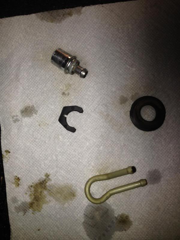
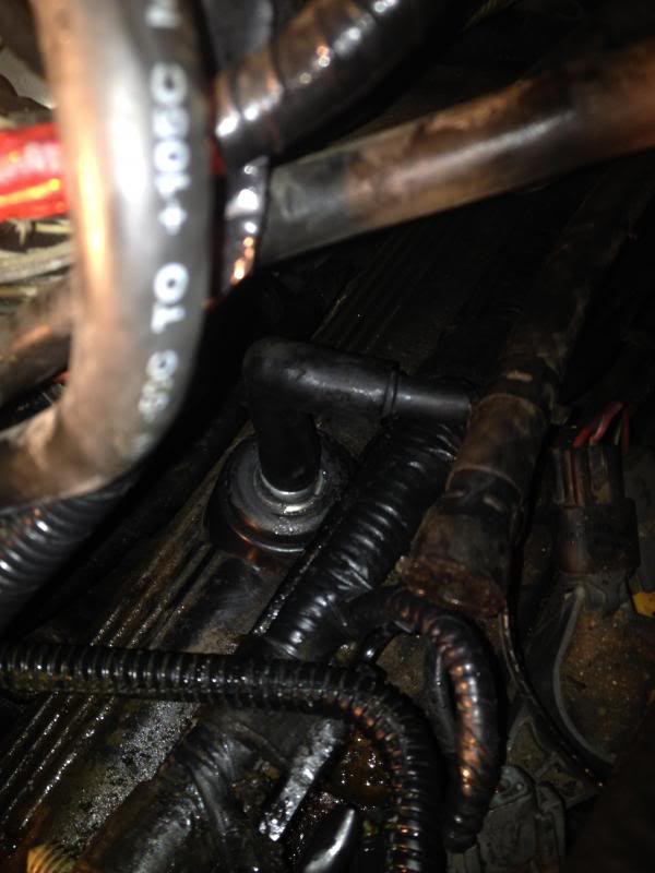
Once all the parts are clean, make sure to clean off the Valve Cover opening for the gromment and replace it.
I used a little bit of sealant around the grommet and PCV Valve to help, mainly bevause these should be replaced whenever you do a change. Along with the hoses connecting them to the throttle body housing.
Name:  IMG_0652.jpg
Views: 10213
Size:  48.3 KB

4) Engine Coolant Temperature (ECT) sensor


How it works.

Your ECT sensor simply works on resistance and sends that to the PCM then to your gauge. The sensor uses a thermistor which is more accurate at smaller intervals than other types of simple resistance based temperature gauges.

A thermistor is a type of resistor whose resistance varies significantly with temperature, more so than in standard resistors. The word is a portmanteau of thermal and resistor. Thermistors are widely used as inrush current limiters, temperature sensors, self-resetting overcurrent protectors, and self-regulating heating elements.

Thermistors differ from resistance temperature detectors (RTD) in that the material used in a thermistor is generally a ceramic or polymer, while RTDs use pure metals. The temperature response is also different; RTDs are useful over larger temperature ranges, while thermistors typically achieve a higher precision within a limited temperature range, typically −90 °C to 130 °C.
http://en.wikipedia.org/wiki/Thermistor
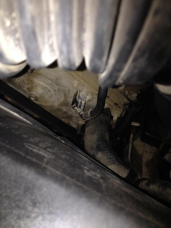
Where is your ECT located?

On my 2003 5.4L it is located on the front of the engine on the drivers side. See picture below for reference.
Name:  IMG_0682.jpg
Views: 10057
Size:  36.8 KB

How can I check it?
First you need to check two things:
1) That your Sensor is working properly, we will use a resistance test for this
2) Check that the plug to the ECT Sensor has voltage.

Checking for a good ECT sensor and plug.
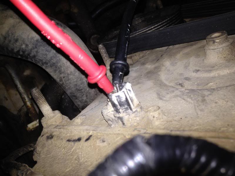
1) To see that the sensor is working proper unplug the connector, it should only have two terminals on it. (This is with the enginge off). Now with the connector off, prob the terminals of the sensor. Place the positive lead on the right hand side and negative lead on the left as show below.
Name:  IMG_0689.jpg
Views: 10169
Size:  51.7 KB

Your resistance reading in OHMs should be 60,000 - 40,000 ohms at around 50 degrees Fahrenheit. If it is colder outside your resistance will be higher, so dont worry, that is the way this system works.

Now with everything out of the way let the truck idle until it gets to operating temperate. One it gets to operating temperate re-do step (1) and prob the terminals to check resistance again. Your resistance readings should be between 4,000 and 1,700 ohms from 180-220 degrees F. So it is obvious that resistance increases the colder the engine is, but resistance decreases with an increase in temperature.

It is around 55 degrees here now so I was expecting a resistance reading of around 30,000-40,000 ohms.
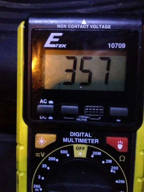
Name:  IMG_0685.jpg
Views: 10052
Size:  53.7 KB
So I can see that my sensor is working properly.

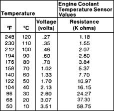
Below is a general physics depiction of the process a guide that can be use to approximate. (This can depend on elevation and of course your model) This is just a general idea, so as long as the resistance is changing adequately, you should be fine.
Name:  ENGINGECOOLANT.jpg
Views: 10424
Size:  12.3 KB

2) Now all we need to do is prob the connector to make sure that it is getting ~5.0 volts. Simply use your DMM to prob the connector and see what you get. The dark green wire should read +5.0 volts.
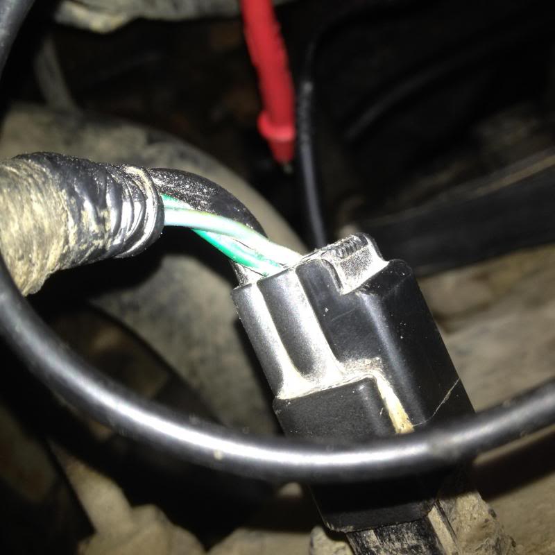
Name:  IMG_0692.jpg
Views: 10236
Size:  54.4 KB

Last edited by ibd2328; 01-20-2014 at 08:57 PM.
The following 3 users liked this post by ibd2328:
Blondie70 (06-03-2021), Boom Bostic (09-01-2019), Ryanzach92 (08-09-2021)
Old 01-19-2014, 10:23 PM
  #5  
Senior Member
Thread Starter
iTrader: (2)
 
ibd2328's Avatar
 
Join Date: Mar 2012
Posts: 8,374
Received 524 Likes on 387 Posts

Default

new
Attached Images
File Type: jpg
IMG_9501.jpg (63.1 KB, 1996 views)
File Type: jpg
MAF.jpg (68.3 KB, 2042 views)
File Type: jpg
IMG_9505.jpg (45.5 KB, 1860 views)
File Type: jpg
IMG_9503.jpg (56.9 KB, 1797 views)
File Type: jpg
IMG_9508.jpg (52.2 KB, 2222 views)
File Type: jpg
IMG_9510.jpg (31.0 KB, 1811 views)
File Type: jpg
IMG_9514.jpg (67.9 KB, 1844 views)

Last edited by ibd2328; 10-07-2017 at 12:48 AM.
The following users liked this post:
Boom Bostic (09-01-2019)
Old 01-19-2014, 11:37 PM
  #6  
Senior Member
Thread Starter
iTrader: (2)
 
ibd2328's Avatar
 
Join Date: Mar 2012
Posts: 8,374
Received 524 Likes on 387 Posts

Default

new.
Attached Images
File Type: jpg
IMG_9518.jpg (56.8 KB, 1871 views)
File Type: jpg
IMG_9516.jpg (51.3 KB, 1962 views)
File Type: jpg
IMG_9515.jpg (55.1 KB, 1993 views)
File Type: jpg
IMG_9520.jpg (61.5 KB, 2053 views)
File Type: jpg
IMG_9511.jpg (57.2 KB, 1826 views)

Last edited by ibd2328; 10-07-2017 at 12:49 AM.
The following users liked this post:
Boom Bostic (09-01-2019)
Old 01-20-2014, 10:00 AM
  #7  
Resident Worm Drowner
 
Ringleader's Avatar
 
Join Date: Jan 2014
Location: West Virginia
Posts: 6,778
Received 90 Likes on 63 Posts

Default

Can't wait to see this finished! Thank you!
Old 01-20-2014, 12:15 PM
  #8  
Senior Member
 
DanielElfert's Avatar
 
Join Date: Apr 2013
Posts: 441
Received 19 Likes on 16 Posts
Default

This should be a sticky lol
Old 01-20-2014, 05:53 PM
  #9  
Senior Member
Thread Starter
iTrader: (2)
 
ibd2328's Avatar
 
Join Date: Mar 2012
Posts: 8,374
Received 524 Likes on 387 Posts

Default

New
Attached Images
File Type: jpg
TPS.jpg (10.7 KB, 2727 views)
File Type: jpg
IMG_0657.jpg (79.6 KB, 2344 views)
File Type: gif
TPStypicaldiagram.gif (16.2 KB, 6077 views)
File Type: gif
tpspoteminater.gif (18.9 KB, 2480 views)
File Type: jpg
IMG_0656.jpg (50.0 KB, 1869 views)
File Type: jpg
TPSLABELED.jpg (59.3 KB, 1974 views)

Last edited by ibd2328; 10-07-2017 at 12:50 AM.
The following users liked this post:
Boom Bostic (09-01-2019)
Old 01-20-2014, 08:15 PM
  #10  
Senior Member
Thread Starter
iTrader: (2)
 
ibd2328's Avatar
 
Join Date: Mar 2012
Posts: 8,374
Received 524 Likes on 387 Posts

Default

Everything is done up to the 02 sensors. Comments, suggestions, or additions are welcome.
The following 4 users liked this post by ibd2328:
Boom Bostic (09-01-2019), Michael_in_DE (06-20-2017), msantello (11-16-2016), wilson84 (12-25-2014)


Quick Reply: EGR, EVAP, PCV, ECT, 02's, TPS, IAT


All times are GMT -4. The time now is 01:58 PM.