Wiring up running board LED's... need wiring advice! - SOLVED
#1
Certified Cow Porker
Thread Starter
Vehicle: 2015 F-150 XLT Extended Cab 5.0 4x4
I've put in LED strips for the underside of my running boards and I'm running into a bit of a hiccup on the wiring. The endgame is to have these strips illuminate the ground whenever you open a door or hit the unlock key, then turn off when you start driving or lock the doors. Here's how I have it set up now:
Running Light Circuit (Input Signal) > Relay > LED strips
This turns them on properly and works fine during the day when the running lights turn off as you start the engine. The problem I'm having is that at night the running lights kick on automatically with the headlights, and that lights up the LED strips as an unintended side effect. I'm not interested in underglow and I'd prefer these strips stay off when I'm moving. Although I could easily put in a manual kill switch for the LED's, I want this to be automated. I'd also like to avoid disabling my running lights.
I had a few ideas as to how to solve this problem. Unfortunately, this truck being a redesigned model makes it hard to get my hands on any sort of wiring diagrams or how-to guides/videos showing what I need to see. This is what I thought of, but do not have the necessary information to do:
1. Tap into dome light circuit
or
2. Tap into daylight sensor circuit (only if it's a "hot" signal during the day)
or
3. Tap into the bed light circuit (white bulb above the back window)
... and use that as an activation signal for the LED relay. I checked the fuse location that powers the dome lights and this appears to be an "always hot" feed, ruling it out as a candidate for a fuse tap.
If you have any suggestions on how to properly wire this, or know where I can find schematics showing the physical location of options 1-3, that would be appreciated. I'd prefer not to rip out my headliner to get access to the end of the dome light circuit. Thank you for your advice!
Jake
See Link: https://www.f150forum.com/f118/wirin...2/#post4374897
Last edited by ymeski56; 10-16-2015 at 09:05 PM.
The following users liked this post:
nardog (12-21-2015)
The following users liked this post:
J15 (09-30-2015)
#3
Certified Cow Porker
Thread Starter

The following 3 users liked this post by fordworker:
#5
Certified Cow Porker
Thread Starter
Would you mind deciphering that for me? I didn't spend much time on electrical work in engineering school. In other words, what physical location can I go to for a signal, and what fuse or wire am I looking for? I'm indifferent as to which option (1-3) we go with, or if there's a better solution. Point me in the right direction so I can start soldering 
Thanks for playing 20 questions haha!

Thanks for playing 20 questions haha!
#6
Would you mind deciphering that for me? I didn't spend much time on electrical work in engineering school. In other words, what physical location can I go to for a signal, and what fuse or wire am I looking for? I'm indifferent as to which option (1-3) we go with, or if there's a better solution. Point me in the right direction so I can start soldering 
Thanks for playing 20 questions haha!

Thanks for playing 20 questions haha!
#7
Certified Cow Porker
Thread Starter
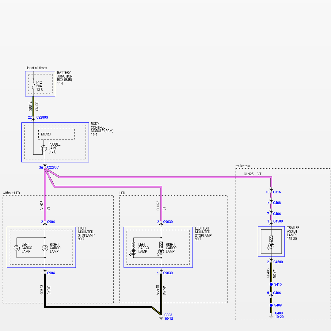
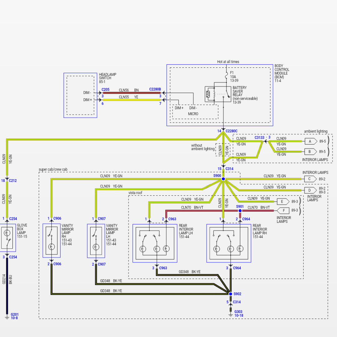
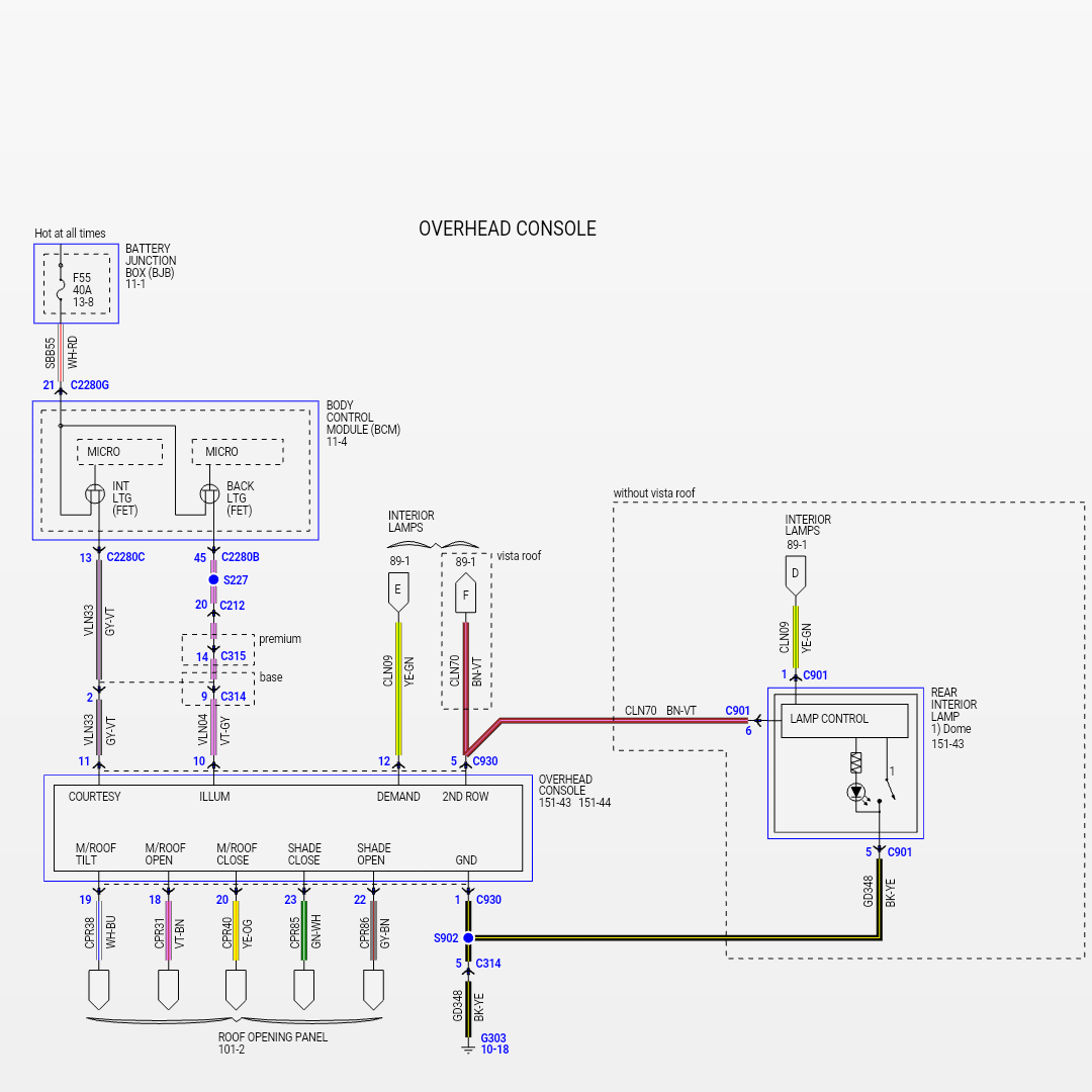
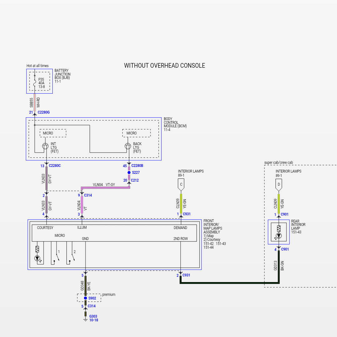
Well if you're looking into splicing into the cargo lamp circuit that would be the VT wire. The dome light it would be YE-GN circuit. I'm not a guru when it comes to the add on stuff but I would be concerned with putting an overload on those circuits which could do something to your bcm. ...but it might not do anything to it I honestly don't know.
Is there any sort of diagram that shows the way these wires are physically routed? A pillar, rear pillar, door sill, etc. I presume I'm looking for a yellow wire.
Trending Topics
#8
All about PurPlazur
The easiest way is to tap the wires for the courtesy floor lights. Problem with the XLT is that we don't have them. Never the less, the electrical connector is there waiting for the fixture. Look just under the dash for a rectangular opening. That's the place the light clips in. Between this opening and the console or mid-dash if you don't have the console, there are two connectors plugged into a plastic receptacle that goes nowhere. One of them is the courtesy light. Don't remember which one tho but you can find out using a tester.
Or do as I did, I crawled under the dash of a King Ranch in the dealer showroom to locate everything ;-)
Or do as I did, I crawled under the dash of a King Ranch in the dealer showroom to locate everything ;-)
#9
You're absolutely right on the overload concerns and that's why I'm running a relay to control the LED's. I ran a fused power line from the battery directly to the LED relay. Anything I splice into will be used purely for signal and not for powering the devices. This has the added benefit of letting me splice into whatever I want for a signal. The problem isn't about knowing what circuits I need to access. The dome light and cargo light will both work. The problem is physically locating and accessing these circuits as their end position (nearest the bulbs) aren't easy to get to, and their connections at the fuse box are always hot. In other words, I need to tap into their power wires at the harness before their bulbs so I can skip any excessive disassembly.
Is there any sort of diagram that shows the way these wires are physically routed? A pillar, rear pillar, door sill, etc. I presume I'm looking for a yellow wire.
Is there any sort of diagram that shows the way these wires are physically routed? A pillar, rear pillar, door sill, etc. I presume I'm looking for a yellow wire.
The following users liked this post:
J15 (09-30-2015)
#10
Certified Cow Porker
Thread Starter
The easiest way is to tap the wires for the courtesy floor lights. Problem with the XLT is that we don't have them. Never the less, the electrical connector is there waiting for the fixture. Look just under the dash for a rectangular opening. That's the place the light clips in. Between this opening and the console or mid-dash if you don't have the console, there are two connectors plugged into a plastic receptacle that goes nowhere. One of them is the courtesy light. Don't remember which one tho but you can find out using a tester.
Or do as I did, I crawled under the dash of a King Ranch in the dealer showroom to locate everything ;-)
Or do as I did, I crawled under the dash of a King Ranch in the dealer showroom to locate everything ;-)


