When you click on links to various merchants on this site and make a purchase, this can result in this site earning a commission. Affiliate programs and affiliations include, but are not limited to, the eBay Partner Network.
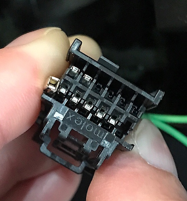
Did you remove the front white plastic pin guide from the connector? It makes insertion easier.
To get the correct orientation, I know it's difficult, try to look at how the pins to the left/right in the connector are inserted. They can only go one way as they lock into place. Once rientaion is determined, a small jewelers flat head can assist with full insertion into the connector, but you have to know the orientation 1st or you will destroy the pin wire. (A few others had this slight issue also, but they eventually figured it out) don't give up, lol your close.
To get the correct orientation, I know it's difficult, try to look at how the pins to the left/right in the connector are inserted. They can only go one way as they lock into place. Once rientaion is determined, a small jewelers flat head can assist with full insertion into the connector, but you have to know the orientation 1st or you will destroy the pin wire. (A few others had this slight issue also, but they eventually figured it out) don't give up, lol your close.
Thanks. Well despite your best efforts and making this as foolproof as possible of a mod I ended up destroying a couple pins. That said I had no trouble getting connected to C210 wires and confirmed with a meter they are working. I've buttoned everything up and will regroup and conquer this another day.
When I had to swap pins for my tow mirrors (autofold mod) I had no problems pulling and inserting those but these just seemed a bit too snug. I appreciate all you've done as there are a lot of success stories on this thread all thanks to you.
did you get any of themy in? How many were destroyed?
On some trucks, for some reason they are tight. Pin wires are 100% correct. Don't worry, I'll take care of you either way.
2 were destroyed and the third is a bit bent from multiple attempts...so in essence all three as I had a bit of breakdown after the frustrating afternoon. I take full responsibility for the user error here. Either direction it only went in about 1/2 way before getting stuck. I'm open to any and all ideas to move forward here.
I can usually McGyver my way out of almost any of these situations but not this time.
I'm having the same issue with the pins. They are quite obviously different than the pins that are in the connector already. I'm not saying they won't work, but they don't seem to fit. I have re-pinned connectors before and they should slide in and click with little resistance.
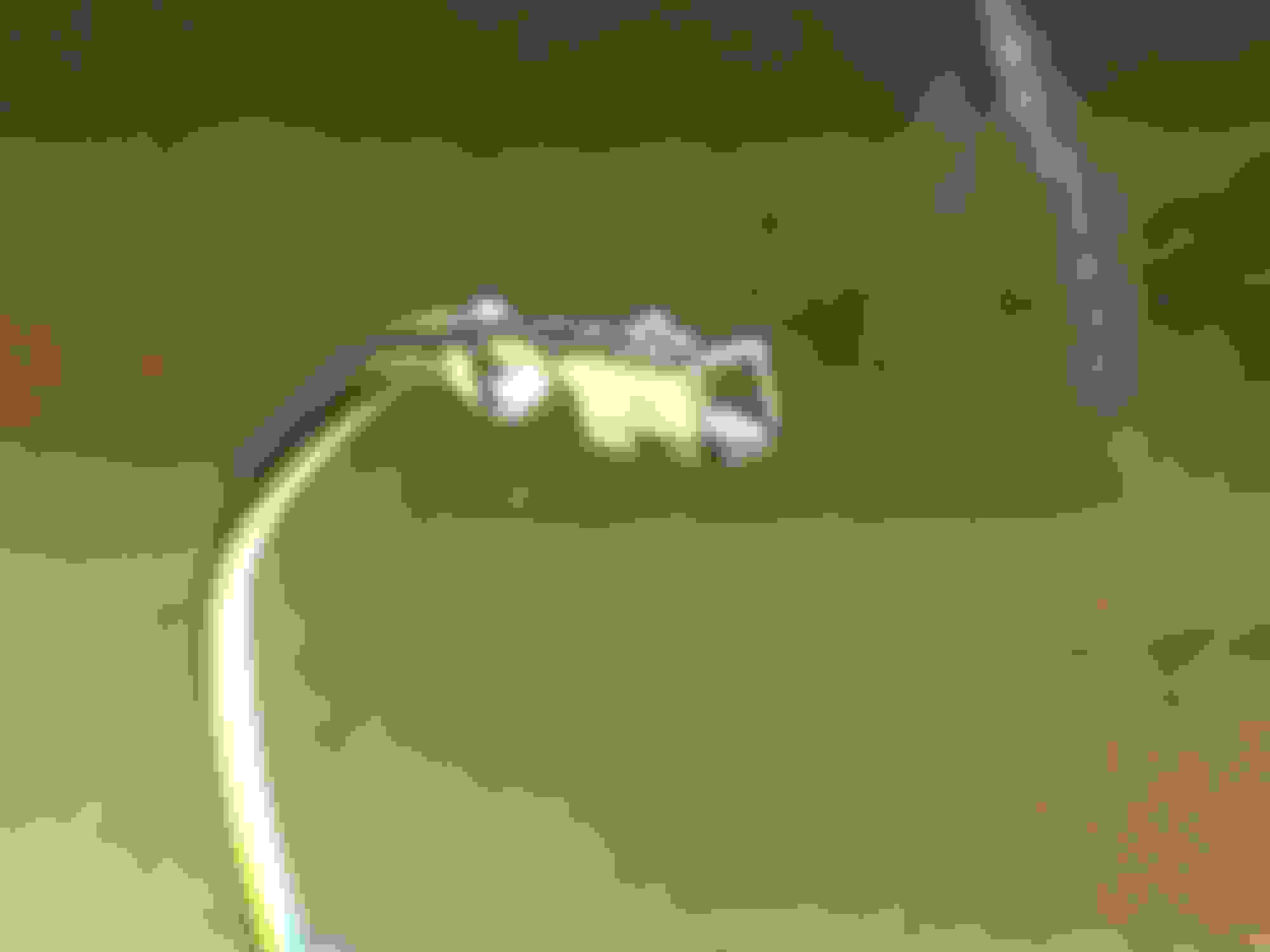
Here is a pic with me holding one of the new pins next to the connector. You can see hopefully that the new pins are basically symmetrical. The existing pins are not, and they also seem to be a bit more narrow. I am leery to shove harder than I already have...they don't seem to want to go.
Here is one I plan to use. I took it from a radio connector. It does look different from the one on the left.
I don't know...this one looks closer to what is in there now. Are you saying this is from another Ford connector?
I'm wondering if it would be a total waste of time to go some where like Radio Shack (do those exist anymore?) and see what they have and get a bunch of samples. Now that I have my BGG cable routed, I'd rather not pull it out to compare (though, if these pins aren't going to work, I guess they could be cut off for comparison...).

 08-05-2017, 02:34 PM