Remote Starter- How to
 03-18-2013, 12:57 PM
#1

Remote Starter- How to: For most 97-03 F150's.
This one is specific for my 2003 FX4 5.4L
I used the following kit from Autozone for ($79.99). It requires you to lose a programmed key(in the bypass module), but it also allows you to crank your truck with "CUT" keys from Lowe's to crank it afterwards. So, you truly don't lose a key.
The one I used: (Cheap Route)
http://www.autozone.com/autozone/acc...er=417767_0_0_
Other options:
http://www.autozone.com/autozone/acc...er=632152_0_0_
http://www.autozone.com/autozone/acc...er=389051_0_0_
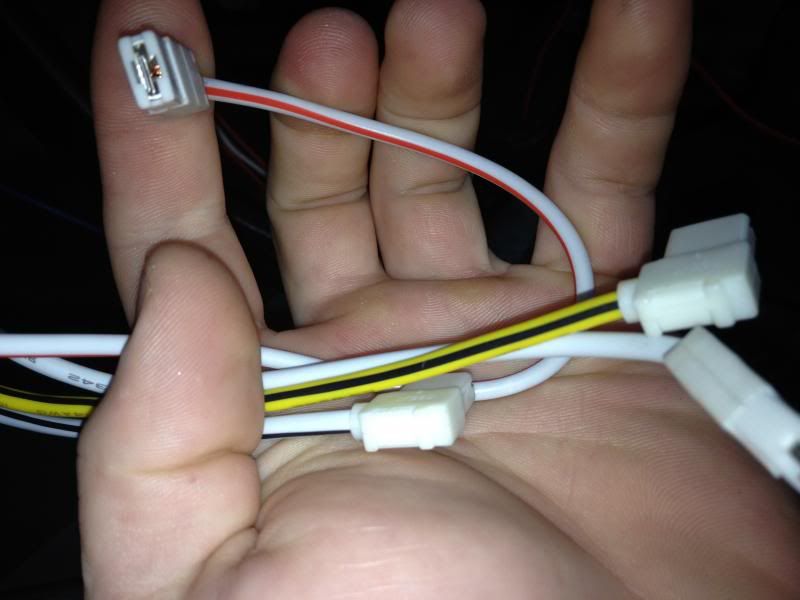
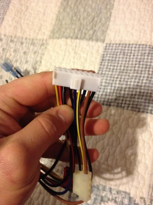
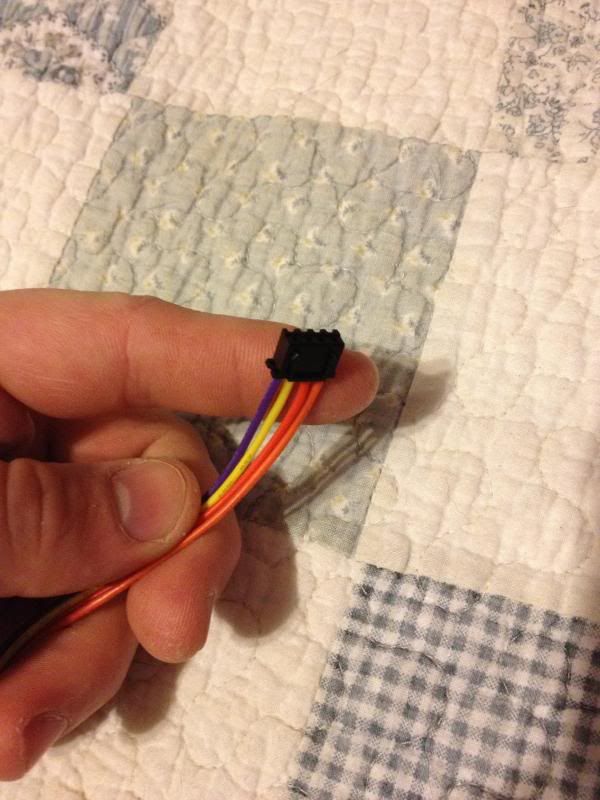
The kit I used will have the following materials all included. (Couldn't find a pic with all the materials, so I added the transponder ring wire to pic)
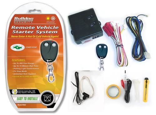
Once you open your kit, you need to organize the wires accordingly.
1) Put the Large gauge wires together. These are all separate wires and only have a single pin molex plug on one end.
-Both Fused Red Wires
-White
-White/Red
-White/Black
-Yellow/Black
2) 9-pin harness:
3) 4-pin plug:
4) Transponder key ring: (loop of wire) with a plug on one end.
5) Module itself
Additional materials:
General socket set
Screwdrivers
Electrical Tape
Wire Cutters
Small Zip ties
A roll of small gauge wire (I used 18ga)
Velcro/Screws for attaching module to the truck (under the dash)
Lets get started: An open/clear place to work and splice wires.
*****DISCONNECT NEGATIVE BATTERY TERMINAL*******
The first thing you need to do is take off the plastic shroud surrounding the steering wheel. We will also need to take off some of the shrouds over the ignitions wires and fuse box in a moment.
Here is how: (thanks to fairlaner) for some of the pics and info
1) Remove the steering column opening cover.
Simply pull up from the bottom to remove the top shroud cover around the shift lever
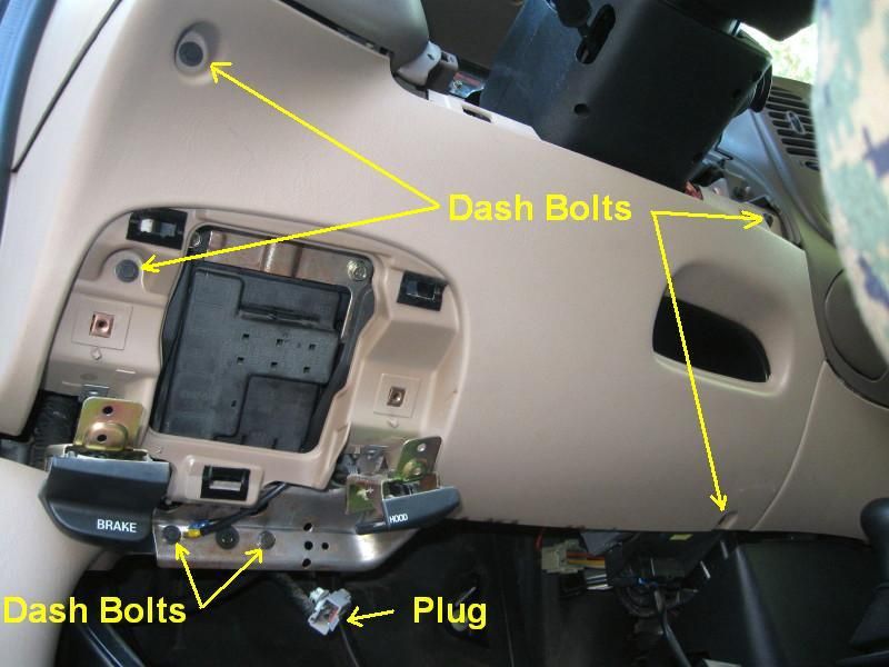
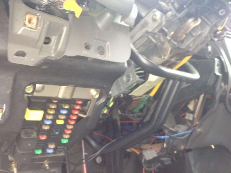
2) Remove the lower instrument panel steering column cover to make it easier to get to the ignition wires and plug.
Remove fuse panel cover
Remove unused gray electrical connector from the lower instrument panel cover
Remove 2 screws (7mm) holding hood release lever
Remove 2 screws (7mm) holding parking brake release lever
Remove 6 screws (2 - 8mm, 4 - 7mm) holding lower instrument panel cover
Remove lower instrument panel cover
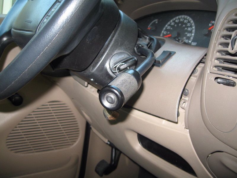
3)Remove ignition switch lock cylinder
Turn the ignition to RUN position
Insert a thin punch(or small screwdriver)into hole in bottom of steering column cover to push the release pin.
Pull out the ignition switch lock cylinder while pushing in the release pin
4) Remove 3 screws (Philips) and remove the upper steering column cover.
[IMG]http://i1147.photobucket.com/albums/o544/bklb28/Remote/shroud3.jpg[
/IMG]
5) Once the 3 screws and ignition cyclinder is removed you will need to take off the steering wheel tilt ****. It simply unscrews, use a pair of pliers on the metal part.
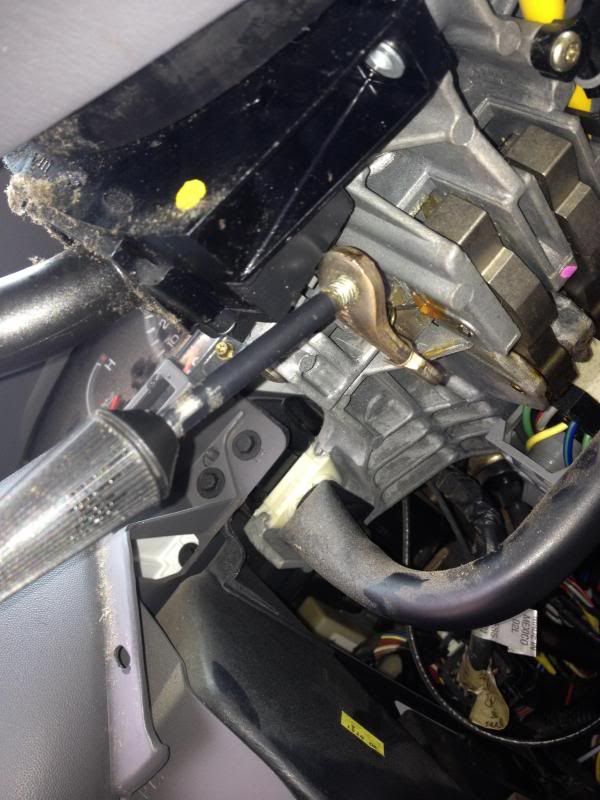
We now have an open station to work with.
This one is specific for my 2003 FX4 5.4L
I used the following kit from Autozone for ($79.99). It requires you to lose a programmed key(in the bypass module), but it also allows you to crank your truck with "CUT" keys from Lowe's to crank it afterwards. So, you truly don't lose a key.
The one I used: (Cheap Route)
http://www.autozone.com/autozone/acc...er=417767_0_0_
Other options:
http://www.autozone.com/autozone/acc...er=632152_0_0_
http://www.autozone.com/autozone/acc...er=389051_0_0_
The kit I used will have the following materials all included. (Couldn't find a pic with all the materials, so I added the transponder ring wire to pic)
Once you open your kit, you need to organize the wires accordingly.
1) Put the Large gauge wires together. These are all separate wires and only have a single pin molex plug on one end.
-Both Fused Red Wires
-White
-White/Red
-White/Black
-Yellow/Black
2) 9-pin harness:
3) 4-pin plug:
4) Transponder key ring: (loop of wire) with a plug on one end.
5) Module itself
Additional materials:
General socket set
Screwdrivers
Electrical Tape
Wire Cutters
Small Zip ties
A roll of small gauge wire (I used 18ga)
Velcro/Screws for attaching module to the truck (under the dash)
Lets get started: An open/clear place to work and splice wires.
*****DISCONNECT NEGATIVE BATTERY TERMINAL*******
The first thing you need to do is take off the plastic shroud surrounding the steering wheel. We will also need to take off some of the shrouds over the ignitions wires and fuse box in a moment.
Here is how: (thanks to fairlaner) for some of the pics and info
1) Remove the steering column opening cover.
Simply pull up from the bottom to remove the top shroud cover around the shift lever
2) Remove the lower instrument panel steering column cover to make it easier to get to the ignition wires and plug.
Remove fuse panel cover
Remove unused gray electrical connector from the lower instrument panel cover
Remove 2 screws (7mm) holding hood release lever
Remove 2 screws (7mm) holding parking brake release lever
Remove 6 screws (2 - 8mm, 4 - 7mm) holding lower instrument panel cover
Remove lower instrument panel cover
3)Remove ignition switch lock cylinder
Turn the ignition to RUN position
Insert a thin punch(or small screwdriver)into hole in bottom of steering column cover to push the release pin.
Pull out the ignition switch lock cylinder while pushing in the release pin
4) Remove 3 screws (Philips) and remove the upper steering column cover.
[IMG]http://i1147.photobucket.com/albums/o544/bklb28/Remote/shroud3.jpg[
/IMG]
5) Once the 3 screws and ignition cyclinder is removed you will need to take off the steering wheel tilt ****. It simply unscrews, use a pair of pliers on the metal part.
We now have an open station to work with.
Last edited by ibd2328; 03-19-2013 at 12:53 AM.

The following users liked this post:
Tackle (03-18-2013)
03-18-2013, 12:57 PM
#2
Wiring 
First we will concentrate on (1) The larger gauge wires you have separated.
Fused Power
Constant Power Wires (The Two "Fused" Red Wires) from the kit
This connection will read +12V with key in any position including off.
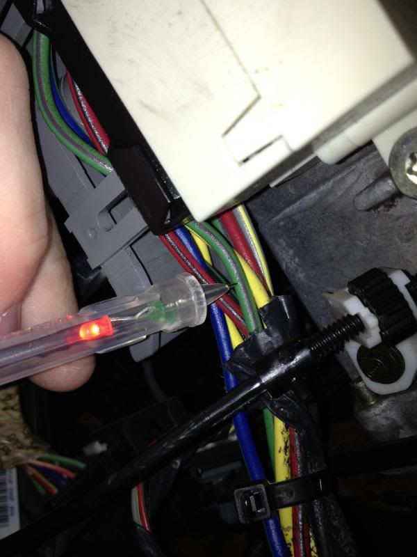
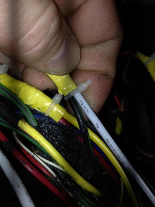
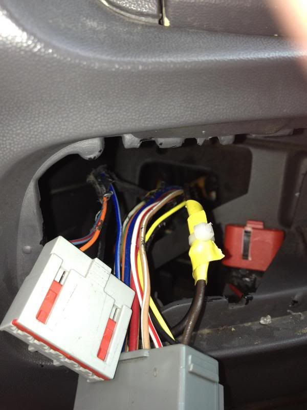
a) Use the Green/Purple wire in the ignition harness(see pic below) to splice into.
b) Run your own +12V wire from the battery (I did this option)
The following 4 wires will all be connected to wires in the ignition harness.
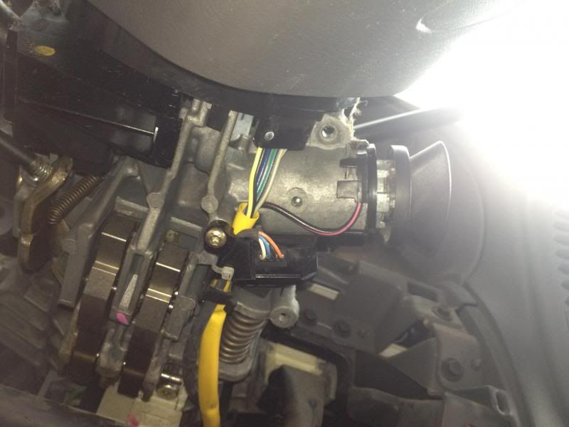
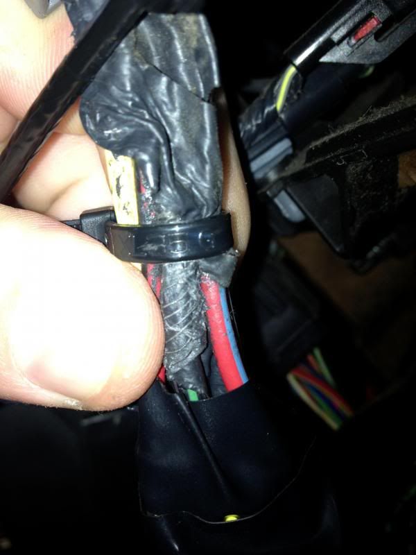
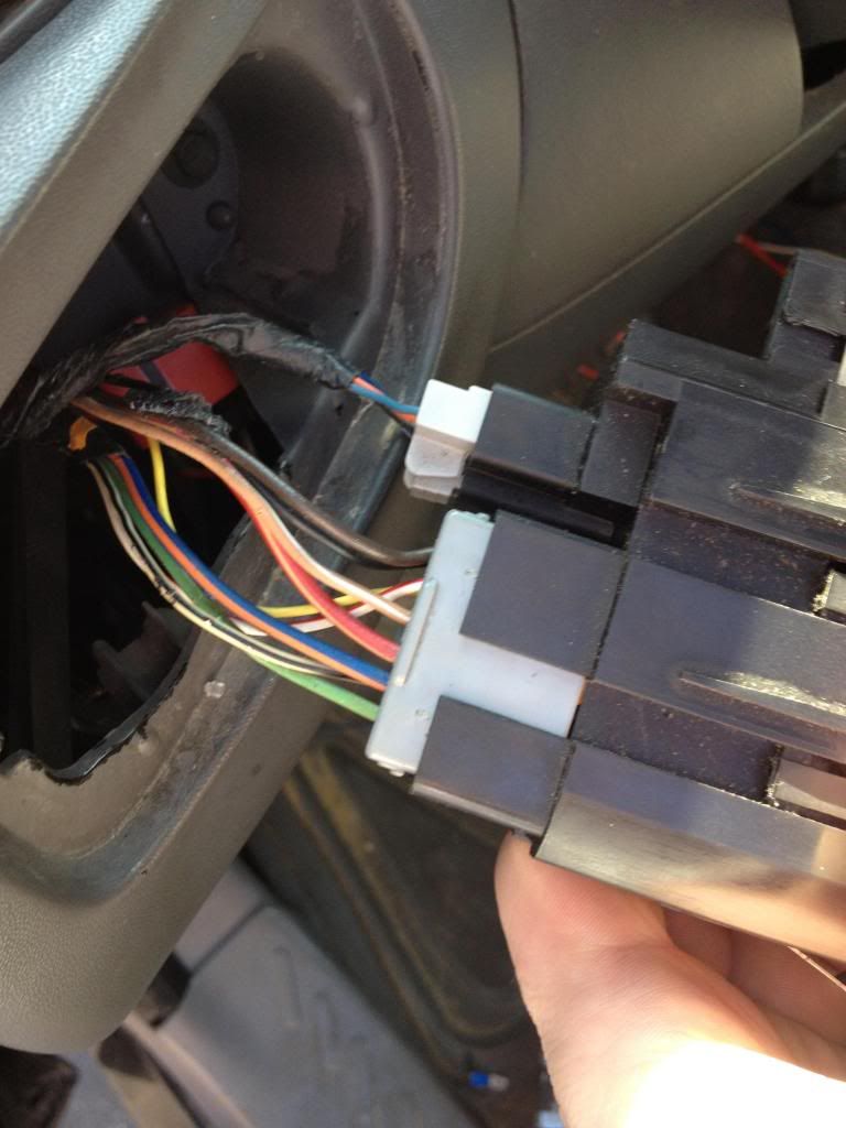
Wires for reference:
Here is the ignition wires/harness.
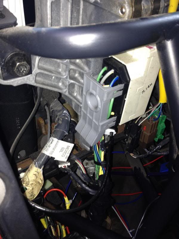
Ignition Wires
Ignition wires ((White) and (White/Red Stripe), both are of larger gauge)
This connection will only read +12V with key in RUN and CRANK positions.
-We will use 3 of our factory ignition wires. Blue/Green, Gray/Yellow, Red/Black.
Blue/Green = Ignition #1
Grey/Yellow = Ignition #2
Red/Black = Ignition #3
The (White) wire from the kit will be spliced into BOTH, Ignition #1(Blue/Green) and #3(Red/Black). Yes, this means all THREE wires will be tied in together. Cut some of the wire insulation back, and splice all three together.
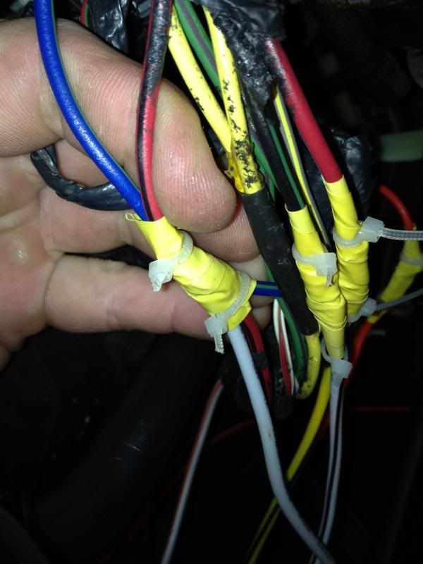
The (White/Red) wire from the kit will be spliced into ignition #2(Grey/Yellow).
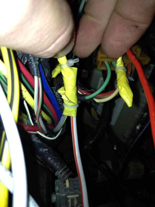
Accessory Wire/s
Larger Gauge (Black/White) wire from the kit.
This connection will read +12V anytime the truck is not turned off.
-Use the (Black/Light Green) wire in ignition harness to splice to the (Black/White) wire from the kit.
Starter/Crank Wire
Larger guage (Yellow/Black) wire from the kit.
This connection will only read +12V when the key is turned over(when the starter is turning).
-Use the (Red/Light Blue) wire in the ignition harness to splice to the (Yellow/Black) wire from the kit
That completes all the ignition harness wiring.
First we will concentrate on (1) The larger gauge wires you have separated.
Fused Power
Constant Power Wires (The Two "Fused" Red Wires) from the kit
This connection will read +12V with key in any position including off.
a) Use the Green/Purple wire in the ignition harness(see pic below) to splice into.
b) Run your own +12V wire from the battery (I did this option)
The following 4 wires will all be connected to wires in the ignition harness.
Wires for reference:
Here is the ignition wires/harness.
Ignition Wires
Ignition wires ((White) and (White/Red Stripe), both are of larger gauge)
This connection will only read +12V with key in RUN and CRANK positions.
-We will use 3 of our factory ignition wires. Blue/Green, Gray/Yellow, Red/Black.
Blue/Green = Ignition #1
Grey/Yellow = Ignition #2
Red/Black = Ignition #3
The (White) wire from the kit will be spliced into BOTH, Ignition #1(Blue/Green) and #3(Red/Black). Yes, this means all THREE wires will be tied in together. Cut some of the wire insulation back, and splice all three together.
The (White/Red) wire from the kit will be spliced into ignition #2(Grey/Yellow).
Accessory Wire/s
Larger Gauge (Black/White) wire from the kit.
This connection will read +12V anytime the truck is not turned off.
-Use the (Black/Light Green) wire in ignition harness to splice to the (Black/White) wire from the kit.
Starter/Crank Wire
Larger guage (Yellow/Black) wire from the kit.
This connection will only read +12V when the key is turned over(when the starter is turning).
-Use the (Red/Light Blue) wire in the ignition harness to splice to the (Yellow/Black) wire from the kit
That completes all the ignition harness wiring.
Last edited by ibd2328; 03-19-2013 at 12:51 AM.
03-18-2013, 12:58 PM
#3
9 Pin Harness Wiring
Note: Some of these wires are optional (*6, 7, *8, 9)
Wire and Function on the Harness
1) Black-Ground
2) Brown- Parking Light Output (+)
3) Black/Blue - Brake Input
4) Yellow/Black - Not needed
5) Blue - Aux input
6)Black/Blue- Hood pin switch
7) Black/White - Tach input
8)Red/Black - Factory Alarm Disarm
9) Yellow- Antenna
Notes:
5 - Not needed unless you have installed an aftermarket alarm.
*6 - Only Install if you want the engine to cut off when the hood is popped or if you don't want auto start to work when the hood is open.
7 - If you want it to start tachless, skip this.
*8- Ford has no such thing as a Alarm Disarm Wire. It does have an alternative and its the Orange/Black wire coming from the alarm system on the drivers side firewall
1) Black- Goes to any ground location. Try to ground it in the drivers kick panel.
2) To properly complete this you will need to do these steps to get to the parking light main switch.
Headlamp switch removal and wiring:
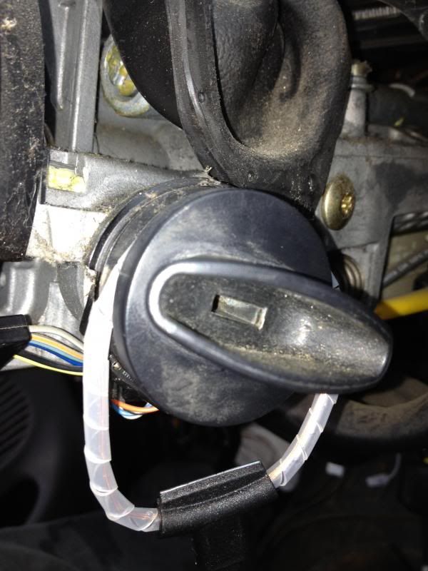
Now we need to concentrate on the headlamp switch.
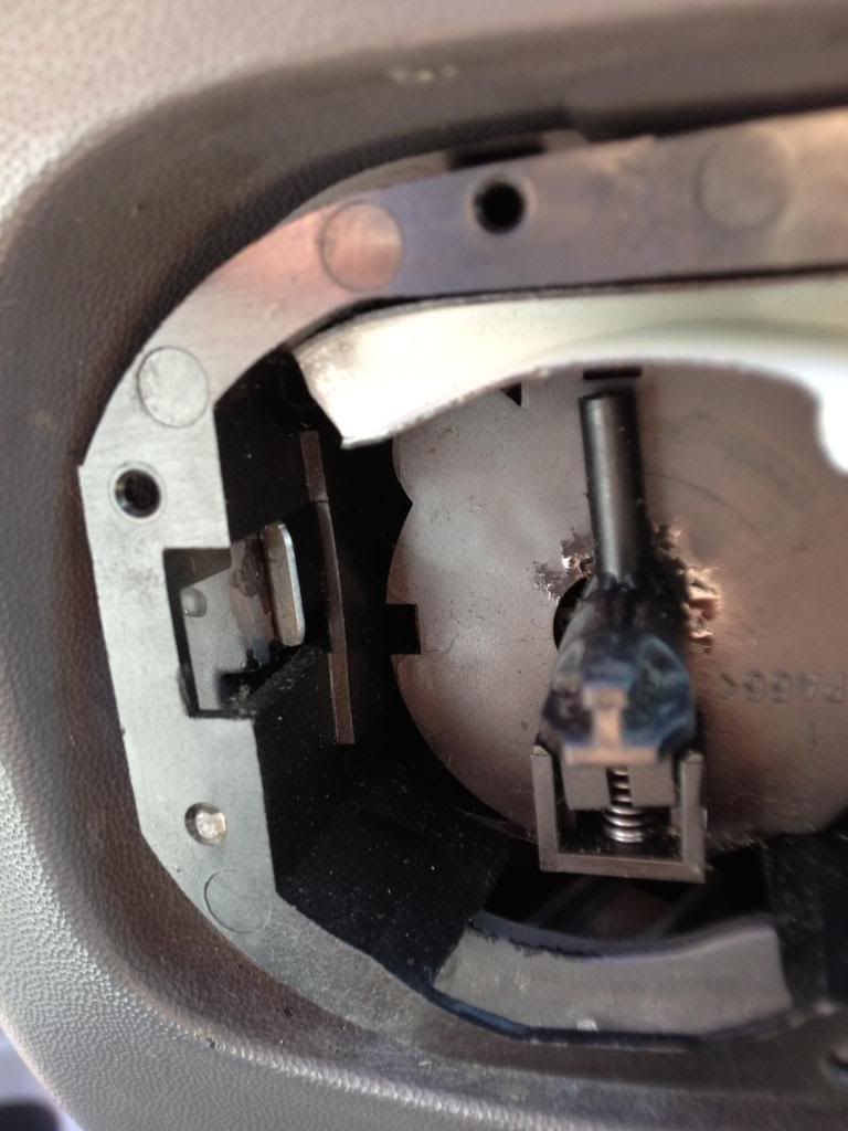
First: Remove the **** on the switch. (just pull slightly)
Second: Remove the outside bezel. (pull slightly or use a flat head)
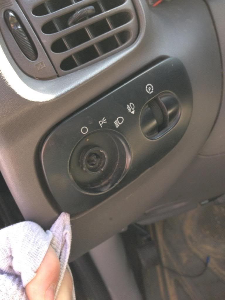
Third: Remove the Switch itself. (There are two prongs you need to lift up to remove the switch)
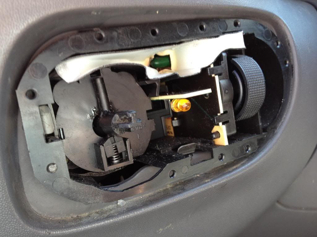
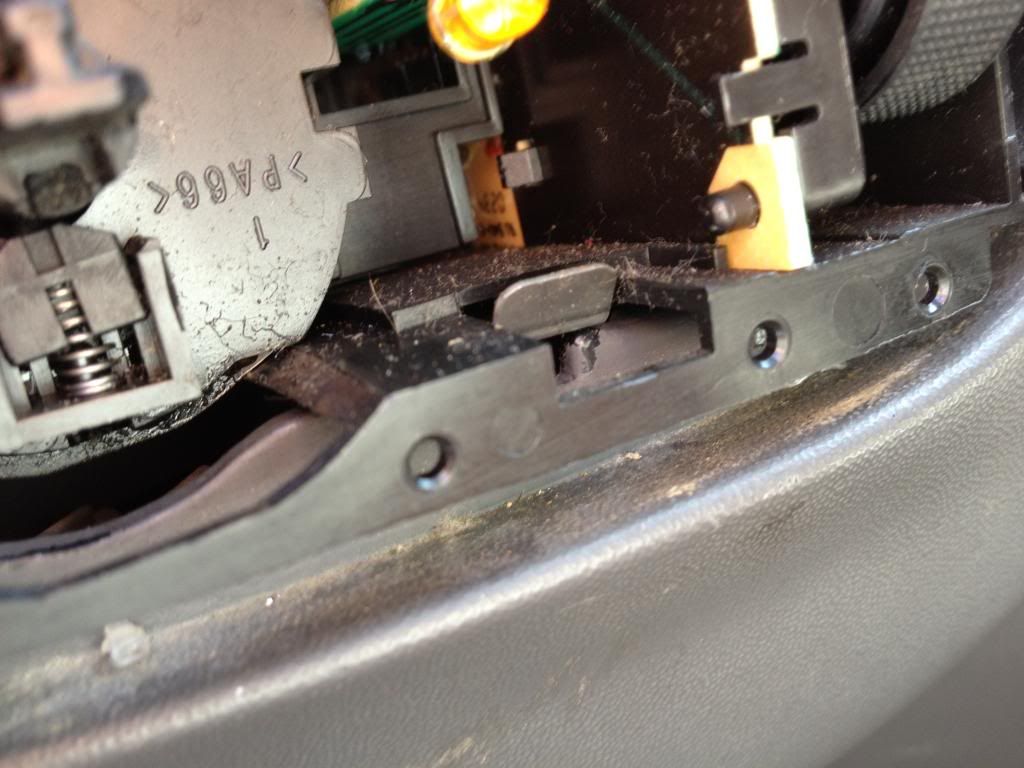
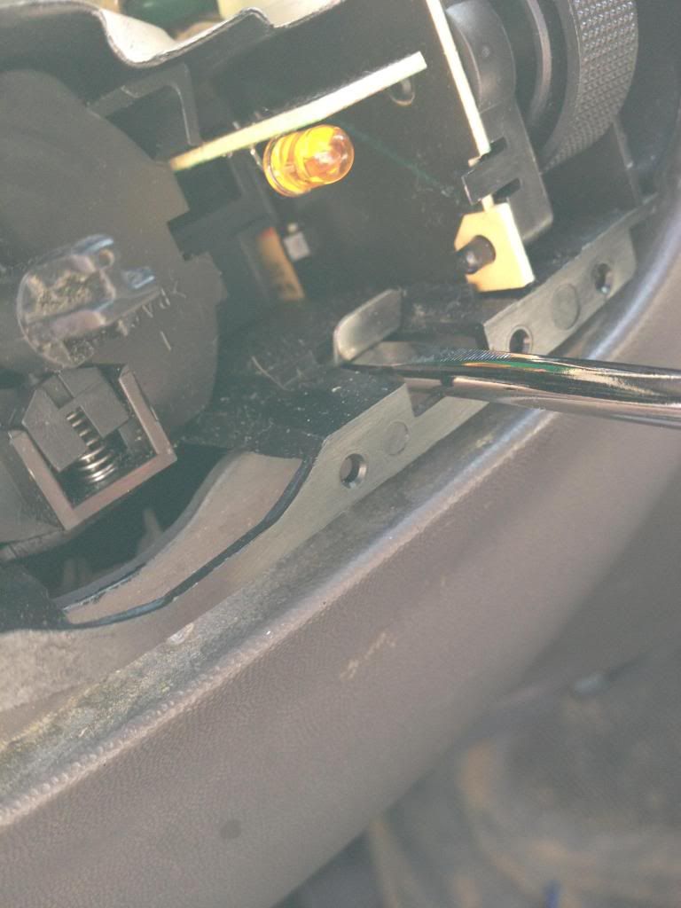
Once you remove the switch platform itself, you will see two connectors on it.
We will only be using the larger plug (the one on the right in the schematic).
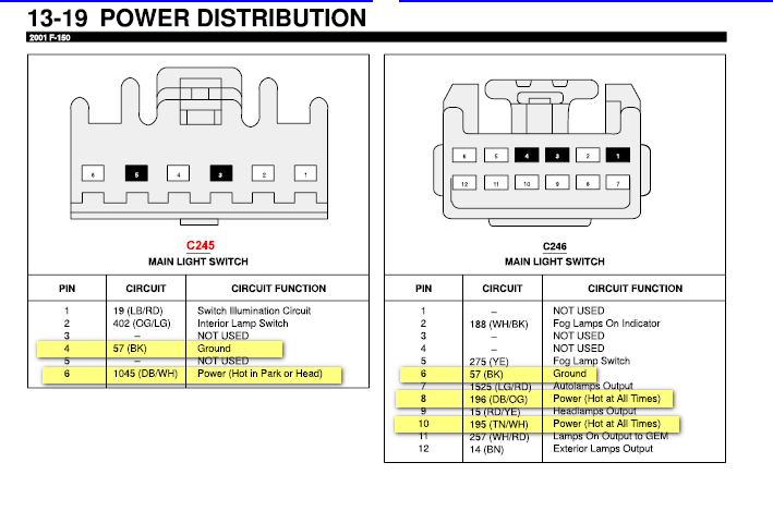
Now, before we splice anything; run a strand of 18ga wire through the opening where we just took out the headlamp switch and thread it down to the kick panel. At the kick panel we will attach this wire to the (Brown) wire on the 9-pin harness.
Cut the access off and splice the other end of the wire to Pin#12(Brown) on the small plug (for the Parking lamps).
Note: Some of these wires are optional (*6, 7, *8, 9)
Wire and Function on the Harness
1) Black-Ground
2) Brown- Parking Light Output (+)
3) Black/Blue - Brake Input
4) Yellow/Black - Not needed
5) Blue - Aux input
6)Black/Blue- Hood pin switch
7) Black/White - Tach input
8)Red/Black - Factory Alarm Disarm
9) Yellow- Antenna
Notes:
5 - Not needed unless you have installed an aftermarket alarm.
*6 - Only Install if you want the engine to cut off when the hood is popped or if you don't want auto start to work when the hood is open.
7 - If you want it to start tachless, skip this.
*8- Ford has no such thing as a Alarm Disarm Wire. It does have an alternative and its the Orange/Black wire coming from the alarm system on the drivers side firewall
1) Black- Goes to any ground location. Try to ground it in the drivers kick panel.
2) To properly complete this you will need to do these steps to get to the parking light main switch.
Headlamp switch removal and wiring:
Now we need to concentrate on the headlamp switch.
First: Remove the **** on the switch. (just pull slightly)
Second: Remove the outside bezel. (pull slightly or use a flat head)
Third: Remove the Switch itself. (There are two prongs you need to lift up to remove the switch)
Once you remove the switch platform itself, you will see two connectors on it.
We will only be using the larger plug (the one on the right in the schematic).
Now, before we splice anything; run a strand of 18ga wire through the opening where we just took out the headlamp switch and thread it down to the kick panel. At the kick panel we will attach this wire to the (Brown) wire on the 9-pin harness.
Cut the access off and splice the other end of the wire to Pin#12(Brown) on the small plug (for the Parking lamps).
Last edited by ibd2328; 03-19-2013 at 03:36 PM.
03-18-2013, 12:58 PM
#4
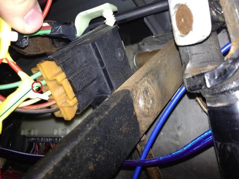
3) Locate the molex plug attached to the top of the hydraulic brake pedal arm. Run a small strand of 18ga wire, spliced from the (light green wire) pin #2 to the kick panel.
4) N/A
5) N/A Don't have an aftermarket alarm
6) You can do this if you choose so. It won't allow the engine to start when the hood is raised.
7) I chose to start my truck Tachless, so this wire is also not needed.
8) Ford Makes no such wire. If they did, PATS would a waste.
9) Yellow- Spread this wire out so your remote can transmit the best signal. Try to stay away from metal parts and keep it straight as possible.
Finished with 9-pin Harness.
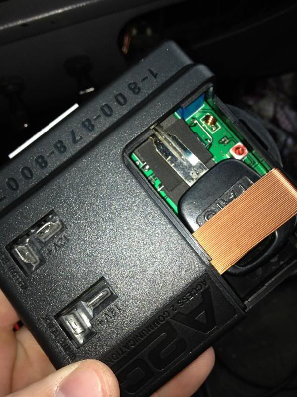
ByPass Module/Transponder
4-pin harness
We will only need Pin 3 and 4 for our next step.
Pin #3= Red This wire will splice into any CONSTANT +12V .
Pin #4= Orange This wire will simply connect to any ground location
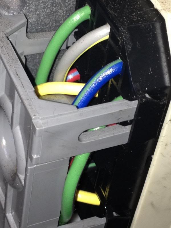
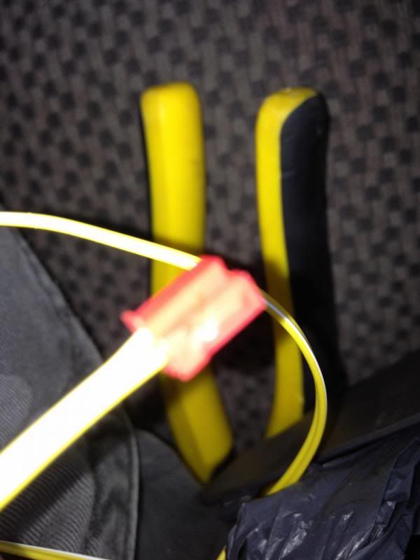
Now, Place your transponder loop wire(yellow and obvious) around the ignition switch. Then run the wires so that they come out at the module itself.
This end should be at the device.
Finished with bypass module.
Finishing up
Go back to the wires 1,2,3 from the 9pin harness. You should have already ran these wires to the kick panel. Attach a 1/4 female connector on the ends of each and attach them to the appropriate wire(double check).
Now attach all larger gauge wires, 9pin harness, 4pin harness, and Key Transponder ring to the module. The module itself gives directions on which plug goes where.
Place your key in the transponder via direction.
Re-attach your neg. battery terminal.
Follow remaining, programming steps in the manual. For the product I used, I only had to hit the rest button on the module 5-times and the LED indicator came on and showed it cleared the resistance code on the PATS module.
Then I used my hand held remote to start up, worked first time!
****DISCLAIMER****
This is my how to, I don't take liability for any damage or injury that may occur when trying to install a remote starter the way I have proposed above. Install at your own risk.
4) N/A
5) N/A Don't have an aftermarket alarm
6) You can do this if you choose so. It won't allow the engine to start when the hood is raised.
7) I chose to start my truck Tachless, so this wire is also not needed.
8) Ford Makes no such wire. If they did, PATS would a waste.
9) Yellow- Spread this wire out so your remote can transmit the best signal. Try to stay away from metal parts and keep it straight as possible.
Finished with 9-pin Harness.
ByPass Module/Transponder
4-pin harness
We will only need Pin 3 and 4 for our next step.
Pin #3= Red This wire will splice into any CONSTANT +12V .
Pin #4= Orange This wire will simply connect to any ground location
Now, Place your transponder loop wire(yellow and obvious) around the ignition switch. Then run the wires so that they come out at the module itself.
This end should be at the device.
Finished with bypass module.
Finishing up
Go back to the wires 1,2,3 from the 9pin harness. You should have already ran these wires to the kick panel. Attach a 1/4 female connector on the ends of each and attach them to the appropriate wire(double check).
Now attach all larger gauge wires, 9pin harness, 4pin harness, and Key Transponder ring to the module. The module itself gives directions on which plug goes where.
Place your key in the transponder via direction.
Re-attach your neg. battery terminal.
Follow remaining, programming steps in the manual. For the product I used, I only had to hit the rest button on the module 5-times and the LED indicator came on and showed it cleared the resistance code on the PATS module.
Then I used my hand held remote to start up, worked first time!
****DISCLAIMER****
This is my how to, I don't take liability for any damage or injury that may occur when trying to install a remote starter the way I have proposed above. Install at your own risk.
Last edited by ibd2328; 03-18-2013 at 01:01 PM.
03-18-2013, 01:06 PM
#5

Well done man! Nice write up.
03-18-2013, 01:06 PM
#6
I found the following codes for an 01, but alot of the models schematics differ. So always use your test light. Mine is a 2003 FX4 5.4
| ITEM | WIRE COLOR |POL| WIRE LOCATION |
| 12V|yellow & lt. grn/pur|+ |ignition harness |
| STARTER|red/lt. blue |+ |ignition harness |
| IGNITION|dk. blue/lt. green |+ |ignition harness |
| SECOND IGNITION|gray/yellow |+ |ignition harness |
| THIRD IGNITION|lt. blue/pink *1 |+ |ignition harness |
| ACCESSORY|red/black |+ |ignition harness |
| SECOND ACCESSORY|black/green |+ |ignition harness |
| POWER LOCK|pink/yellow |*2 |passenger kick panel |
| POWER UNLOCK|pink/green *8 |*2 |passenger kick panel |
| LOCK MOTOR|pink/black | |driver kick panel |
| UNLOCK MOTOR|red/orange | |driver kick panel |
| DISARM DEFEAT|pink/orange | |passenger kick panel |
| PARKING LIGHTS +|brown | |light switch *3 |
| PARKING LIGHTS -|lt. green/yellow | |light switch *4 |
| HEADLIGHTS|red/yellow |+ |light switch |
| DOOR TRIGGER|blk/yel & blk/pnk |- |*5 |
| DOME SUPERVISION|black/lt.blue |+ |passenger kick panel |
| FCTRY ALARM ARM|*6 | | |
|FCTRY ALRM DISARM|dark green/purple |- |drivers kick panel |
| TACHOMETER|*7 | | |
| BRAKE WIRE|light green |+ |at switch *3 |
| HORN TRIGGER|dk. blue |- |steering column |
| WIPERS| | | |
| LF WINDOW UP/DN|org/wht - wht/blk |A |in drivers door |
| RF WINDOW UP/DN|wht/yel - tan/lt.blu|A |drivers kick panel |
| LR WINDOW UP/DN| | | |
| RR WINDOW UP/DN| | | |
The following users liked this post:
slaven14 (05-08-2022)