When you click on links to various merchants on this site and make a purchase, this can result in this site earning a commission. Affiliate programs and affiliations include, but are not limited to, the eBay Partner Network.
I am looking for electrical schematics to diagnose this ??
Yea, you mentioned that at least twice in the thread. Now you have it question form. Where have you looked so far ? Perhaps I can direct you to the manual for your truck. If that's what your looking for, but your not really being clear enough.
White89gt,
thank you, it is the type of schematics that I am looking for.
I have searched the web and forums and seen the schematics that you posted but I need to trace back the provenance of the +12V at the injectors. According to your schematics, I will like to see page 25-1, and page 25-2.
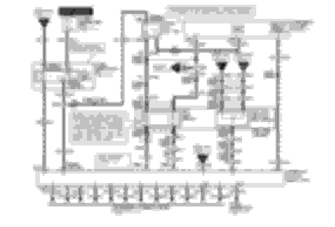
my understanding is that the fuel injectors are powered through the pcm power relay,through a fuse in the battery junction box,
do you have diagrams on the fuse panel + fuse chart? (2001 F150, 5.4L triton bi-fuel)
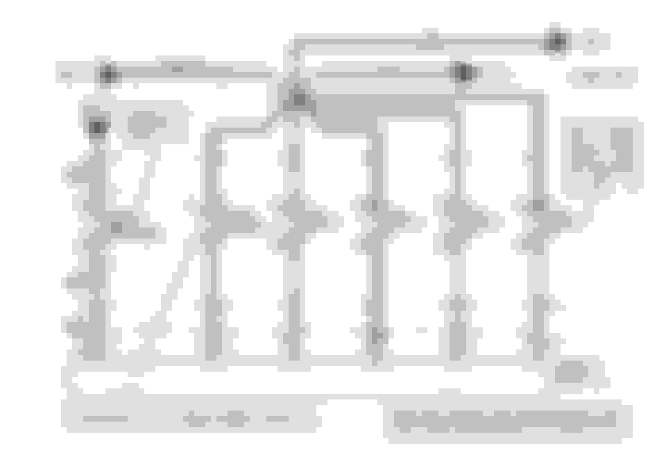
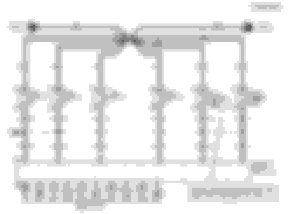
Looking at that 1st and 2nd schematic 361 R is the common feed to each injector, the IAC EGR and a few other things. Nest to where it shows the connector number by each component does it say *2V? I can't tell. IF so that would indicate that that it should have 2V NOT 12V I seem to remember a while ago someone asking how to drop the 12V down to something else to test an injector
Circuit 361 (your 12V supply) between S127 and S129 goes through connector C120 pin 9 as follows:
S127 > C120-9M > C120-F > S129 > S131
Splice Locations (no diagrams available):
S127 - Engine control sensor harness, near T/O to C165 windshield wiper motor
S129 - Fuel charge harness, in T/O to C1012 coil on plug #2
S131 - Engine control sensor harness, near T/O to C165 windshield wiper motor
I'd start by opening C120 and performing a visual inspection of pin 9 of each half. If no faults are obvious, I'd do continuity checks between the C120 pins and the respective splices (or known loads).
ETA: i do not think this is for Bi-fuel, but may help you
Raybz: "Looking at that 1st and 2nd schematic 361 R is the common feed to each injector, the IAC EGR and a few other things. Nest to where it shows the connector number by each component does it say *2V? I can't tell." >> that is +12V, coming from PCM power relay. but I have a hard time reading the pin outs from schematics that I have.
I downloaded the file and will go to mechanic to check it out later.
Thanks
 11-01-2017, 01:13 AM