When you click on links to various merchants on this site and make a purchase, this can result in this site earning a commission. Affiliate programs and affiliations include, but are not limited to, the eBay Partner Network.
"we have adequate oil pressure but I am quite confident it will be fine"
No, its not.
My engine sounded like a diesel until I did a 'partial' timing job. I only did the tensioners and guides AND A NEW HIGH VOLUME PUMP. The tensioners were not blown out. Evidently a previous owner already did the timing work as the phasors were no OEM, nor were the tensioners. The installed ones were identical to the Cloyes ones I was putting in.
The high volume oil pump was responsible for all of the noise going away because nothing else was broken/changed. I didn't plastigauge the cams because I didn't want to mess with the valvetrain.
You will be amazed what the proper amount of oil pressure at idle will do.
its also possible the plastic chain guides broke ( very common fail point in these engines)
And previous owner did not remove the oil pan and remove those pieces of plastic from getting sucked up into oil inlet causing lower pressure �. Agreed the higher volume pumps are great - however, in your case the high volume pump could be just masking this blockage problem as the stock pump may of been fine if your engine is within specs.
Update:
Well, we're still waiting for parts, but my noid light set did come in so we decided to do Brian's test, check the wave form at the solenoid and look into just how we would go about installing the OP gauge. It looks like these noid lights are really designed to check fuel injectors. The one for Bosch injectors had a pin spacing that was a reasonable fit the the solenoid connector. Most high impedance injectors I am aware of have somewhere around 13 ohms coil resistance. We measured our VCT solenoids at ~8.9 ohms. The noid light is just under 4 ohms. We did a KOEO self test with the noid light connected to the right solenoid connector, but as soon as it light up I disconnected it because I was concerned that the low resistance of the light might harm the solenoid driver. Anyway, the fact that it light up was good because that proves we have our 12V supply, the solenoid coil and connections are good and the PCM is completing the circuit by grounding the load side of the coil. But, this doesn't tell us if the PCM is sending the commanded PWM signal or not. To check that I back probed the load side wire at the solenoid connector with a big pin, connected my scope probe to that, and the probe ground to a jumper to ground at the battery. We cleared the codes in the PCM and brake torqued the engine to ~1200RPM. This is just enough to tell the PCM to retard the cam. We had to be careful not to apply too much load because we've found from experience if the VCT error goes beyond ~80% for a not very long period, the PCM says "enough of this" and just disables the VCT and sets the CEL. We had the VCT error and the pulse width up on the scan tool display so we could take note of that as soon as I was able to capture a good signal. This was relatively easy to do. The wave form looked good, calculated frequency was 312.5Hz. Voltage looked right and the calculated duty cycle was 71.8% very close to what we observed on the display. So far everything is still looking like a stuck phaser.
Then we had a closer look at what would be involved in installing the OP gauge. At this point I would like to publicly thank thebestengine for his posts and excellent video. It was very well done and I don't see any way I could improve on anything he has done. I don't think my idea of using grease gun hose will work for several reasons. Things are pretty cramped in there, and quite close to that hot down pipe. I think what he has done with the long loop in the copper tubing addresses any work hardening concerns and the rubber tubing is great for all the reasons he has stated. Well done, and much appreciated!
Update:
Well, we're still waiting for parts, but my noid light set did come in so we decided to do Brian's test, check the wave form at the solenoid and look into just how we would go about installing the OP gauge. ���.
�..�... So far everything is still looking like a stuck phaser.
Then we had a closer look at what would be involved in installing the OP gauge. At this point I would like to publicly thank thebestengine for his posts and excellent video. It was very well done and I don't see any way I could improve on anything he has done. I don't think my idea of using grease gun hose will work for several reasons. Things are pretty cramped in there, and quite close to that hot down pipe. I think what he has done with the long loop in the copper tubing addresses any work hardening concerns and the rubber tubing is great for all the reasons he has stated. Well done, and much appreciated!
Thanks for your nice comments- that�s why we post in hopes to help out others 👍🏻
keep us updated on your progress-
Thanks @E4ODnut for the informative, definitive VVT Solenoid diagnostic test. I would have probably 'guessed' the duty cycle pulses to be around 1000 Hz. But even at the lower 312 Hz, it is kinda sobering how fast the processor is in the PCM. It has to manage 'at least' FIVE of these closed loop systems simultaneously ( Bank1 & 2 Cam positions - to VVT solenoids, Bank 1 & 2 O2 sensors to injectors, and Fuel Pump duty cycle to Fuel Rail pressure sensor. Plus all the other management routines. Buzy little devil.
Update.
We replaced the right side exhaust manifold and I can see why the shops charge several thousand dollars to do this. There were two of us working on it, and granted, we are first timers at this so we were going slow and careful, but it took us 7 hours just to get set up and get the manifold off. As for the studs, #4 top was obviously broken off at the manifold flange, all others appeared to be intact, but as it turned out #1 top was still in place but broken off just inside the head. #2 bottom came out nut and stud. #2 and #3 top just the nut came off. All others twisted off at the manifold flange. It took us another 7 hours to get the studs out and another 12 hours to get things back together. The manifold was leaking at #4 and #1. It also had a crack between #4 and #3 but it didn't appear to be leaking there. I cleaned it up a bit, put it on a known flat surface and had no trouble inserting a .015 " feeler gauge around the #4 and #1 ports.
Before we installed the new Dorman manifold I checked it for straight. It was high on several points on the outside of #4 flange and generally on the other 3. I could fit a .006" feeler on the #4 port and a .004" feeler on a few spots on the #3 port. With the delicate use of a 5" grinder I was able to get it flat all around to the point that I couldn't get a .0015" feeler in anywhere and when I place each port on the feeler it took about the same amount of pressure to withdraw it so I'm confident I'm within ~ .001" of flat all around. I couldn't get as smooth a finish on the flange as I would have liked, but it's pretty good, especially where the gasket seals so I think we'll be OK.
The truck had been sitting for several days during this process and we rather expected to hear some brief noises of some sort until oil pressure built up, but there was nothing, not even a mild ticking like lifters just topping up, so that's good news. We installed a mechanical oil pressure gauge temporarily at the filter housing and brought the engine up to operating temperature . Oil pressure in neutral, ~600 RPM was ~19 PSI. In gear, ~500RPM pressure was ~15 PSI. At 1300 RPM pressure was 45 PSI. The current Ford spec is for a minimum of 15 PSI at idle, so I think the engine is still in acceptable condition in the oil pressure department. It idles and runs absolutely smoothly so we didn't bother with a compression test. Cold or warm, the only engine noise we hear are the injectors, which we confirmed with a stethoscope. Having said all of that, when it is at operating temperature, we can get what we assume is phaser noise at no load, ~1100 RPM. Any faster or slower it goes away.
We are now at the point where we have to decide if we are going to replace the phasers or lock them in full advance and re-flash the CPU to eliminate the CEL codes. I know there have been some spirited discussions on why not to do this, but in all of my research so far I haven't come across anyone who has regretted doing the lockout and re-flash.
Wow you have some time into this project! Seeing you confirmed the pressure is within spec - in your case lock outs would be an economical option for a higher mileage engine and a maintenance history that is not definitively known. As you mentioned earlier that you are avoiding the shotgun approach - investigating not past removal of the valve covers would be throwing $ away to install phasers only without going through the entire timing procedure including installing the HV pump and cast iron RATCHETING tensioners ( the real cure to broken plastic chain guides ).
Last edited by thebestengines; Oct 20, 2021 at 12:52 PM.
Update:
Well, it's been about 3 weeks since we replaced the right exhaust manifold and checked the oil pressure with a mechanical gauge. So far things seem to be static and no exhaust leaks. We still have the CEL and right cam over advanced code. No surprise there. We did an oil change to 5W30 syn. We do get a brief engine clatter on cold start up if the truck has been sitting for a day or more, but it disappears in about 3 seconds. We still have the brief clatter at ~1100 RPM no load, no place else. We installed the mechanical oil pressure gauge permanently it it confirms our initial tests. Cold engine idle is 60 PSI+. At full operating temperature idle in neutral is ~ 19 PSI, in gear is ~ 15 PSI. We've waffled between installing lockouts or staying completely stock and have come to the conclusion that the truck is worth saving and we will stay stock and go with a new OEM timing kit and Melling 340 HV. We are ordering parts and expect to install over the Christmas holidays. We hope to get another ~100,000KM out of the truck so we have to take that into consideration. Oil pressure is acceptable, but barely. At 190,000 KM the engine is probably at least half life so it is doubtful if the timing components will last as long as we want them to. It's ~ $Cdn 2000.00 in parts, but that's just part of owning a 5.4L 3 valve.
As for the oil pressure gauge, we would have preferred to use theb
estengines recommended location to use the right cylinder head port, but that was just too crowded for us, so we opted for the filter housing. We used a 36" grease gun hose at that point and brought it up to a 2 port manifold just in front of the coolant expansion tank. We put the stock OP switch there and used the Bosch 1/8 " copper tube kit to run to the gauge mounted in the left windshield pillar pod. It seems like nothing is easy to do on this truck, but my son in law likes it, and when you're in love... Well, what can I say.
I'll update this when we get the timing kit in, I'm most curious to se what we find with that right phaser.
Update 12/31/21.
Well, this has been quite the experience!
We left off in October, waiting for parts to do a complete timing job as per Makuloco's 4 part series. The engine had a slight rattle on start up for a few seconds. It also had a slight rattle at ~ 1100 RPM no load. Other than that it ran well, though Mark thought it should have more power, but he is coming from a Dodge 5.7 Hemi so it might not be a fair comparison. Anyway it took about a month for all the parts to come in so we decided to do the installation over the Christmas holidays when he wouldn't need the truck for work. We estimated that it would probably take us about 5 days, because we've never done one of these before so we have to be super careful. When the parts arrived he did a piece count and everything we ordered was there. In the mean time he had put on about another 1700 Km and noticed that the start up rattle might be getting a bit worse, but nothing really alarming. The truck now has 194414 Km on it.
On Boxing day we started into it. It took us a full day just to get things opened up. The engine was a lot dirtier inside than I had expected so I doubt that it was serviced very regularly. With the timing cover off we could see that the right side stationary guide was completely disintegrated and the left side was broken, but still in place. I hadn't really expected that, but now it was obvious that we would have to pull the pan to get rid of the shrapnel and clean the oil pick up screen. We checked the roller followers in place and didn't find anything amiss but intended to pull them all for a good inspection of them as well as the cams. After we got the phasers, chains, guides and tensioners off we unpacked the "OTC-6684" to get started removing the followers. Then the shock happened. Our supposedly new OTC tool was actually some used knock off. We could have lived with that, but it was broken. Some low life had bought the tool, broken it, returned it to Amazon, they presumably inspected it, re-packaged it and sold it to us as a genuine new OTC-6684.
OK, here we are, committed to the job, between Christmas and New years, not an OTC tool to be found anywhere at any price that we could get before needing the truck for work again. What to do? Back to You-Tube to see how the job can be done without removing the followers. That took most of a day to come up with a consensus that we were comfortable with. We then proceeded to get the pan off, which was a pain alright, but we didn't have any severely rusted bolts so it went better than expected. We got the junk out of the pan and screen and installed the new Melling 340HV. Before installing it I took the cover off and packed it with Vaseline. I know Makuloco just advises lubing it with motor oil but I didn't want to take any chances on not getting the pump to prime. Then we rotated the crank so the crank key was at 12 O'clock and the left and right marks on the phasers were at approximately the 11 O'clock and 2 O'clock positions respectively. We marked the cams with reference marks to the cam caps to let us know if they rotated on us and locked them in place with vice grips. We were able to get the chains installed with the link marks with no difficulty and installed the new guides and tensioners.
Before we put the covers back on we did another check to make sure we were timed right and turned the engine over slowly with a wrench on the crank. Then came another scare. After two crank revolutions our chain marks didn't align any more. It took us a while to figure out why. Turns out you have to make 21 complete chain revolutions before they will line up again. The rest of the reassembly was non eventful but time consuming because we kept checking and rechecking our work to make sure we hadn't missed anything. After we had most of the jewelry put back on we did a cold compression test. Fortunately for us the previous owner had new spark plugs installed a few years ago so they came out OK, but they were Champions, so we installed the specified Ford SP-546s. The compression was good, as I had expected because the engine had run so smooth. #1 - 190 PSI, #2 - 170 PSI, #3 - 192 PSI, #4 - 172 PSI, #5 - 176 PSI, #6 - 176 PSI, #7 - 185 PSI, #8 - 186 PSI. Before doing the compression test we had filled the crankcase with fresh 5W30 synthetic oil, and filled the oil filter before installing it. With the plugs out and a fresh battery it cranked for about 15 seconds before we had oil pressure. During the compression test cranking pressure was ~60 PSI.
The big moment finally arrived and we lit the boiler. It fired up right away, nice and smooth, no noises, no check engine lights, no bad stuff at all. Definitely a champagne occasion. The test ride proved to be an unqualified success is (so far, at least, I am a realist). Oil pressure at operating temperature in gear at ~520 RPM is 30 PSI.
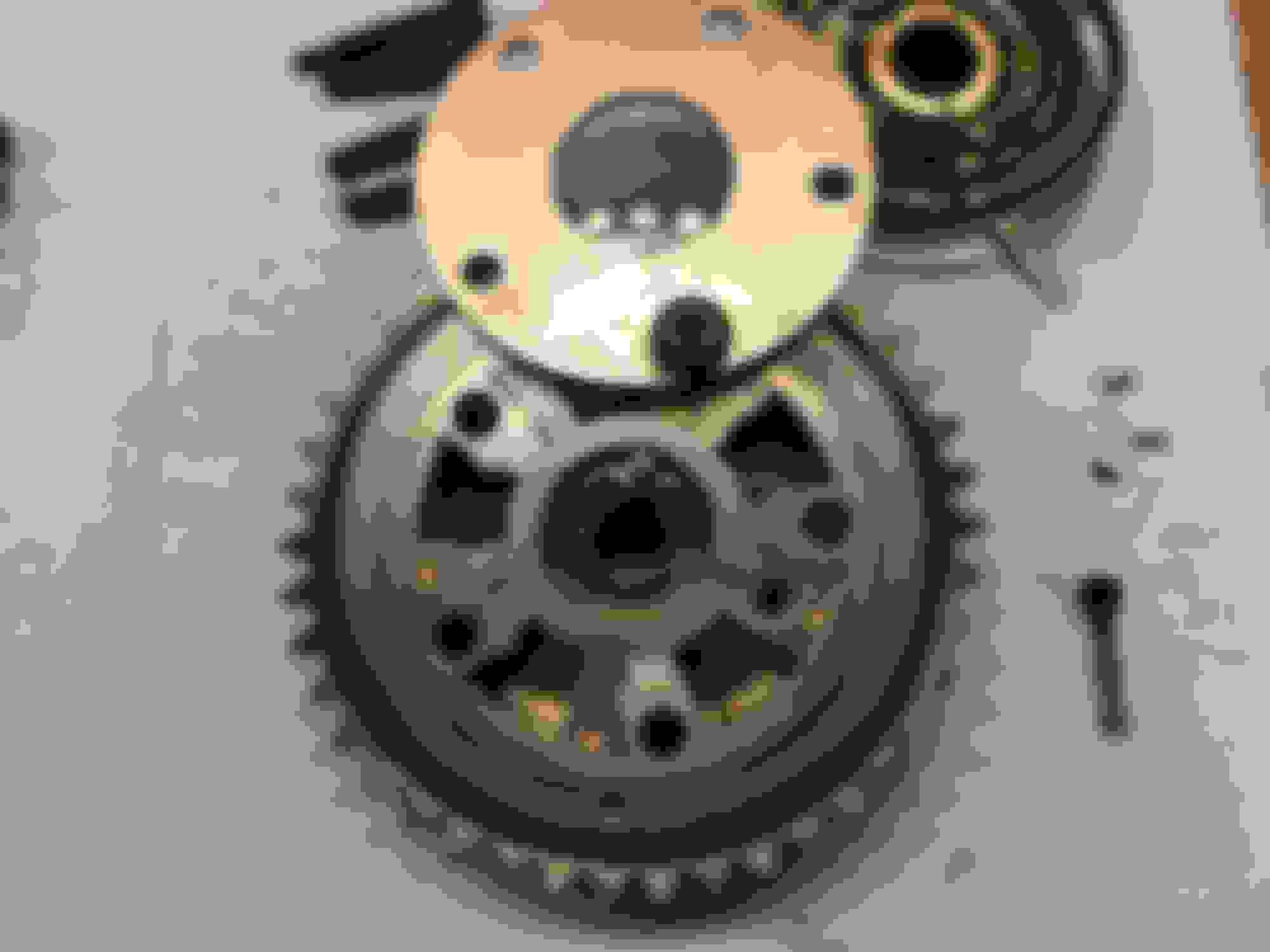
So, now the post mortem. The right phaser gave an initial clue as the centre spoke was not aligned with the mark, as it should have been. The left phaser's centre spoke was aligned the mark as it should be, but the spoke assembly was loose. I clamped the left phaser in a soft jawed vice and removed all the bolts except the long one. I was able to rotate the cover to get the locking spring out and then rotated it out of the way to see what I could see. It didn't take long for me to realize that all 5 of the arms that hold the perimeter seals were broken which had jammed the phaser. When I went to disassemble the left phaser as soon as I took off the intermediate long bolt the spring assembly sprung off. The 3 pins that hold the reluctor to the phaser had backed out. Other than that it looked to be in working order. With the phaser bolted to the cam I don't think that loose pins would have affected anything.
The fact that the right phaser and stationary guide were destroyed bothered me. What could have caused this? When I inspected the tensioners the gaskets were in place, but looked a bit strange. After handling the right tensioner a small piece of gasket did come off, but I don't think that would be enough to cause this kind of carnage. Then I researched exactly how these tensioners are supposed to work. That took some time but eventually I found that they work on the same principal as hydraulic valve lifters. Simplified, it is just a piston with a relatively weak return spring in a cylinder with a check valve to a port which supplies oil pressure. When first installed there is no oil in the chamber and the piston can move in and out depending on the tension of the chain. When oil pressure is applied the air will be displaced by oil to take up the chain slack. The oil remains in the cylinder because of the check valve and effectively makes a solid connection. Unless the piston and cylinder are severely worn or the check valve fails, the tensioner will be able to continually take up any slack in the chain. In order for there to be so much slack in the chain at start up I reasoned that the check valve must have failed and set about to see if I could determine this. I put both tensioners in a container of oil and depressed the pistons. I was able to get the left tensioner to come up solid, but not the right one. From this my opinion is that some time ago the right check valve failed. This means that every time the engine was started it was started with a collapsed tensioner which allowed the chain to slap around until oil pressure built up enough for the tensioner to take up the slack. This repeated abuse eventually destroyed the stationary guide and very likely destroyed the phaser.
Bottom line is, if you own a 5.4L 3 valve and it starts to make an abnormal noise, investigate it and fix it right way, or things will become very costly. This whole procedure took us 5 1/2 days, and ~ Cdn$2500 in parts, but unless something really bad happens we should be able to get at least another 100,000 Km out of the engine, which will probably outlast the rest of the truck. Oh, and don't be scared of pulling the pan, it's not nearly as bad as we thought it would be. The whole procedure is still a major pain, but none of it is as bad as changing an exhaust manifold.
I hope some of this will be of some use to someone.