
Upfitter switch install - wiring help please
 07-02-2016, 03:16 PM
#1
Senior Member
Thread Starter
iTrader: (1)


Hey all:
I have decided to install the upfitter switches I have had in the garage for a couple months now. I have a 2013 XLT with a trailer brake controller. Since I have only ever towed a U-Haul trailer, that didn't have electric brakes, I have decided to remove it and place the upfitter switches in that location in order to have easier access.
Now I have the relays and harness, but instead, I plan to create my own harness. This may be a mistake on my part, but I have already started down this path.
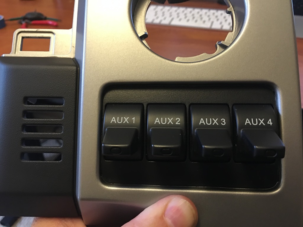
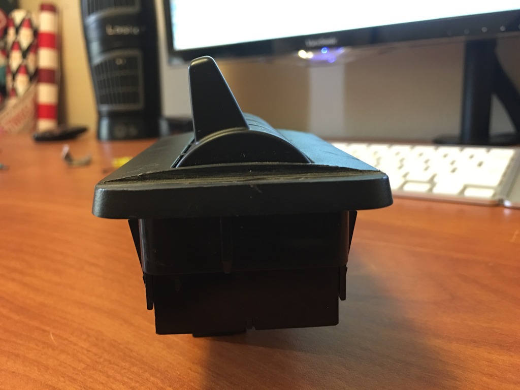
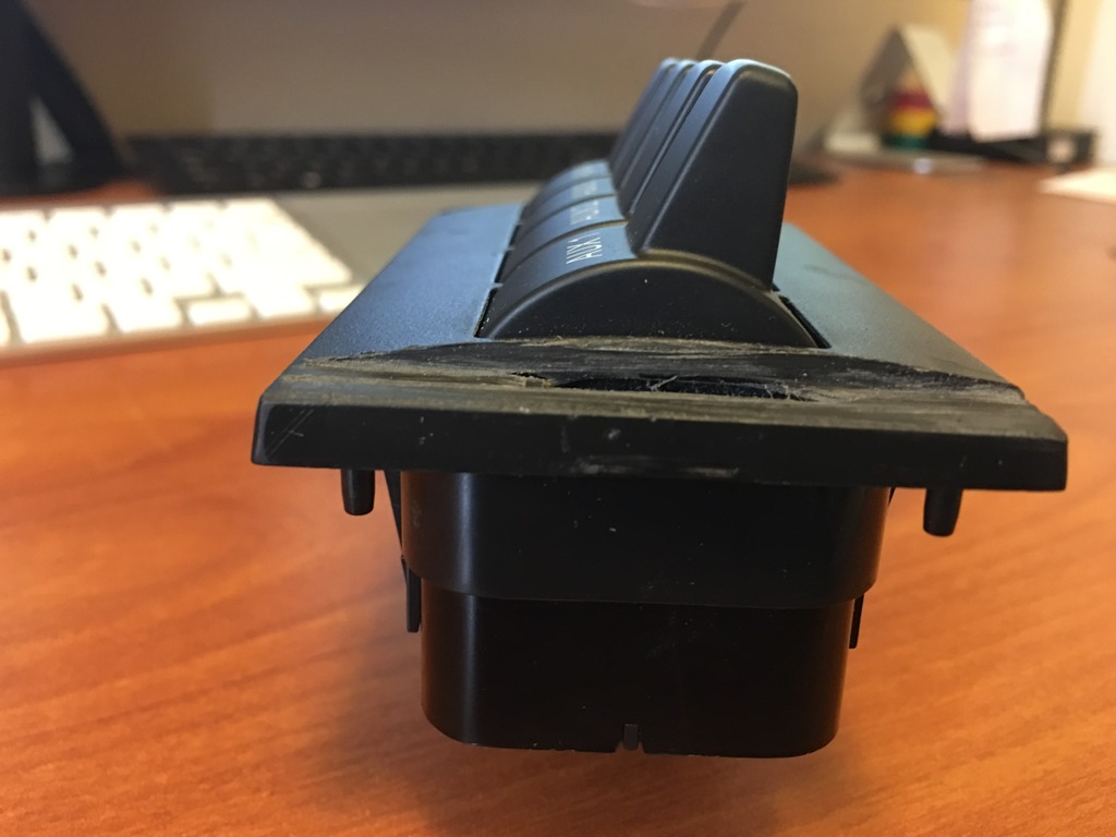
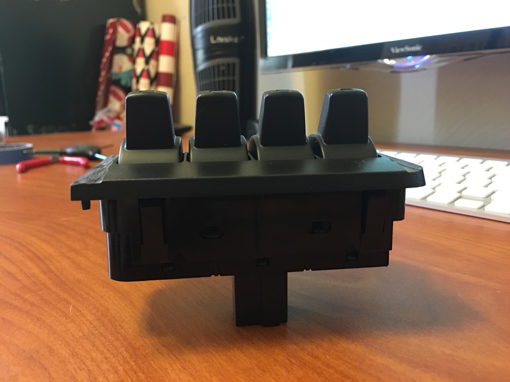
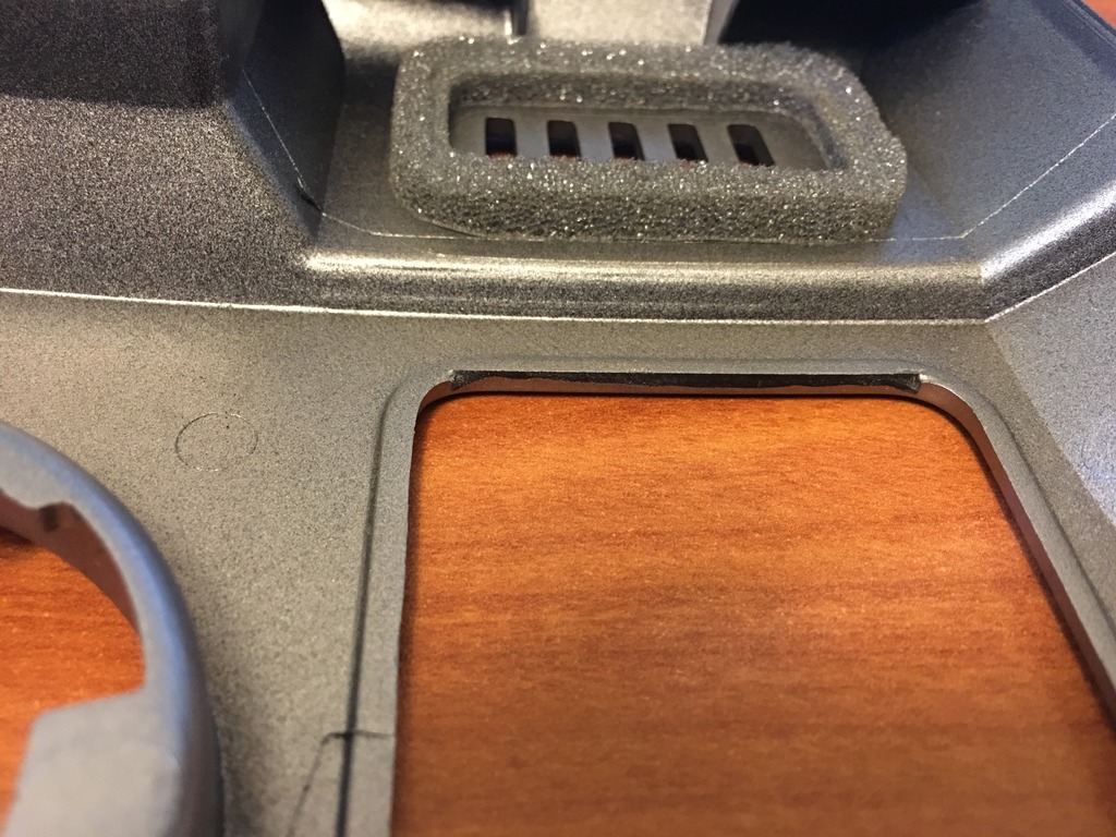
The other advantage to choosing the driver side to mount the switches is there is no cutting of the dash structure behind the trim panel. Plenty of room behind there. The switches do have a curve and do not fit the hole very well, so I cut and filed and trimmed the cover plate on the switches. Here are some photos and the test fit I did. By trimming what I did, I get a much flatter mounting surface on the switches. I also removed a bit of plastic from the back of the trim panel and ever so slightly filed the back edges.
[
Next I will work on mounting the switches with a combination of double-sided tape and JB Weld.
Now, with all of that done, I need to move onto the wiring. As I said, I had the wiring harness and have essentially made myself a pigtail for the 4 switches, ground, illumination, and keyed power. As I just sat in the truck taking out the trailer brake controller and trying to turn it off with the Forscan tool, I had a thought. Could I just pull the ground, illumination, and keyed power out of the TBC connector, move them to the upfitter connector, and not have to do any splicing? However, then I had the thought that if I do that, I will probably lose the keyed power, illumination, and ground when the TBC gets turned off. Am I thinking about that correctly?
I have decided to install the upfitter switches I have had in the garage for a couple months now. I have a 2013 XLT with a trailer brake controller. Since I have only ever towed a U-Haul trailer, that didn't have electric brakes, I have decided to remove it and place the upfitter switches in that location in order to have easier access.
Now I have the relays and harness, but instead, I plan to create my own harness. This may be a mistake on my part, but I have already started down this path.
The other advantage to choosing the driver side to mount the switches is there is no cutting of the dash structure behind the trim panel. Plenty of room behind there. The switches do have a curve and do not fit the hole very well, so I cut and filed and trimmed the cover plate on the switches. Here are some photos and the test fit I did. By trimming what I did, I get a much flatter mounting surface on the switches. I also removed a bit of plastic from the back of the trim panel and ever so slightly filed the back edges.
[
Next I will work on mounting the switches with a combination of double-sided tape and JB Weld.
Now, with all of that done, I need to move onto the wiring. As I said, I had the wiring harness and have essentially made myself a pigtail for the 4 switches, ground, illumination, and keyed power. As I just sat in the truck taking out the trailer brake controller and trying to turn it off with the Forscan tool, I had a thought. Could I just pull the ground, illumination, and keyed power out of the TBC connector, move them to the upfitter connector, and not have to do any splicing? However, then I had the thought that if I do that, I will probably lose the keyed power, illumination, and ground when the TBC gets turned off. Am I thinking about that correctly?
Last edited by larryo108; 07-02-2016 at 03:19 PM.
 07-05-2016, 06:50 PM
#2
Senior Member
Thread Starter
iTrader: (1)
I am not getting much help, so I have done some further research. Even if I could get the keyed power, illumination, and ground by transferring the wires from the trailer brake controller plug to the upfitter plug, the pins are not the same size. So it will not work. I am leaning towards building my own harness and connections. I do have the upfitter harness, but I have already made cuts to the wires and would prefer not to solder them back together. I could, but I like clean wires from plug to plug with no breaks.
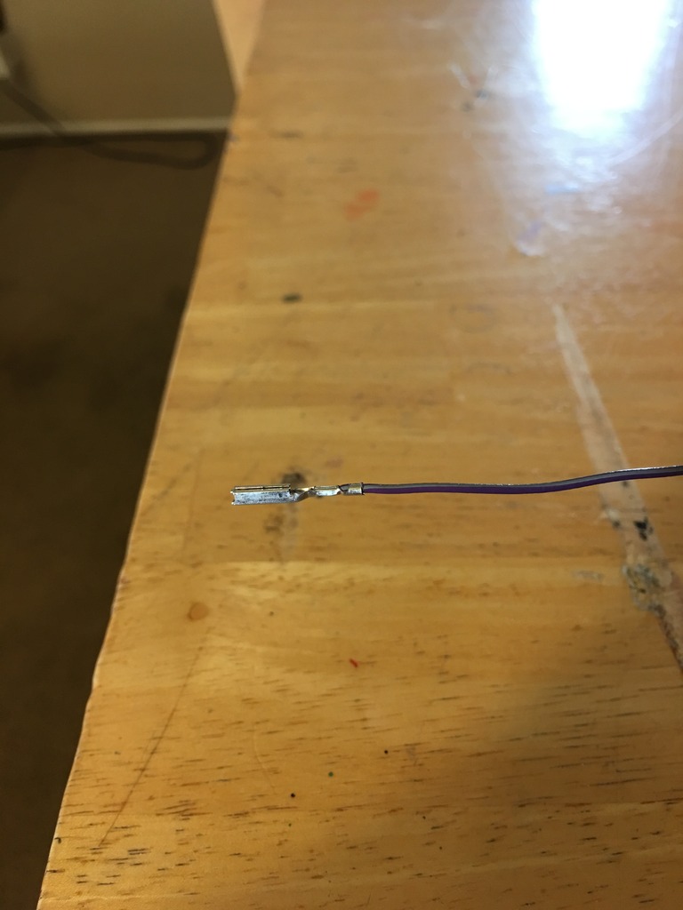
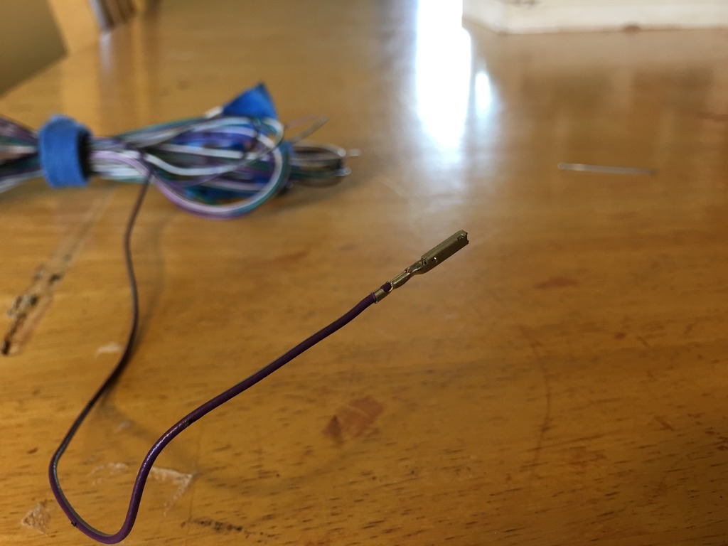
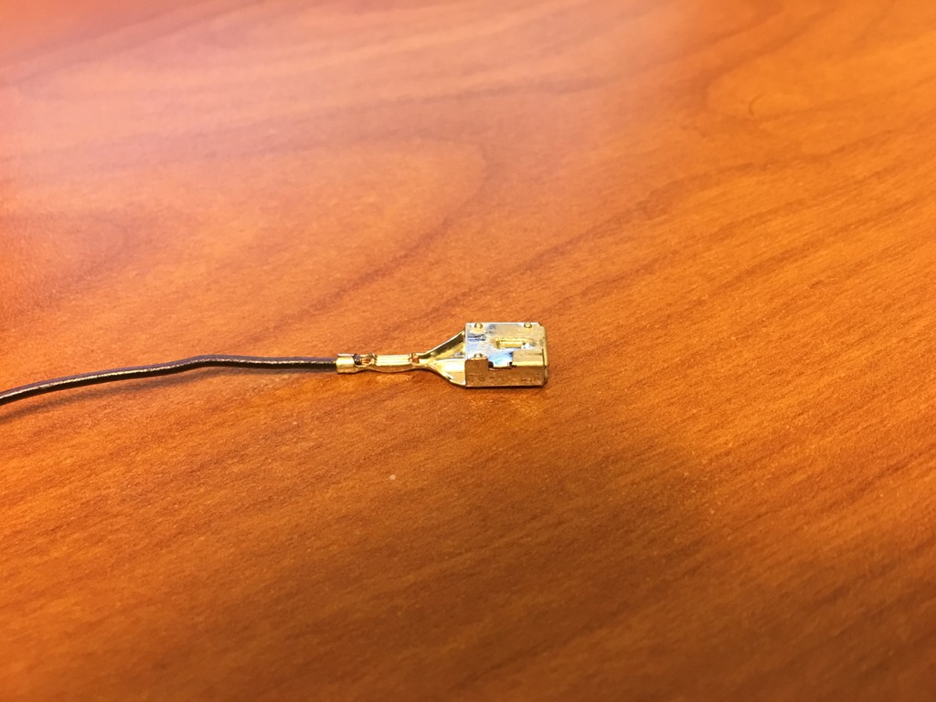
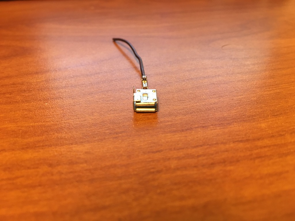
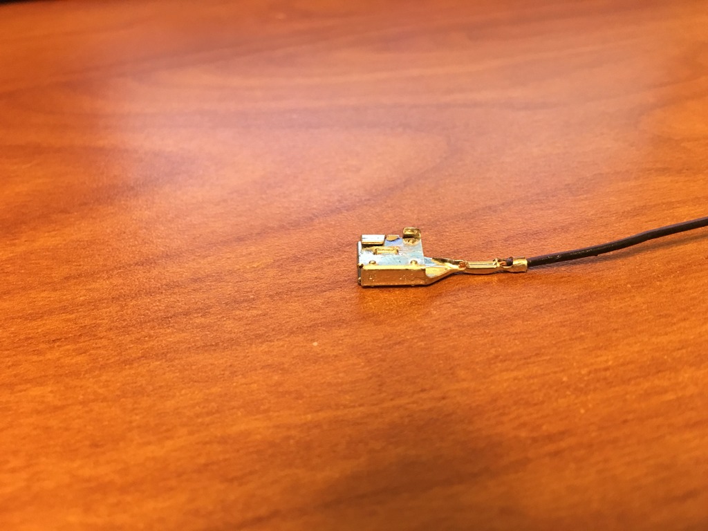
I also wanted to size up the wiring from the plug at the switches to the relays. I have managed to remove the pins from the plug and am now on the search for new pins so I can build my own wiring. The pins measure out to about 2mm by 2mm square and about 8mm deep. Does anyone know where I might be able to find a pin connection like this? This can't be specific to Ford.
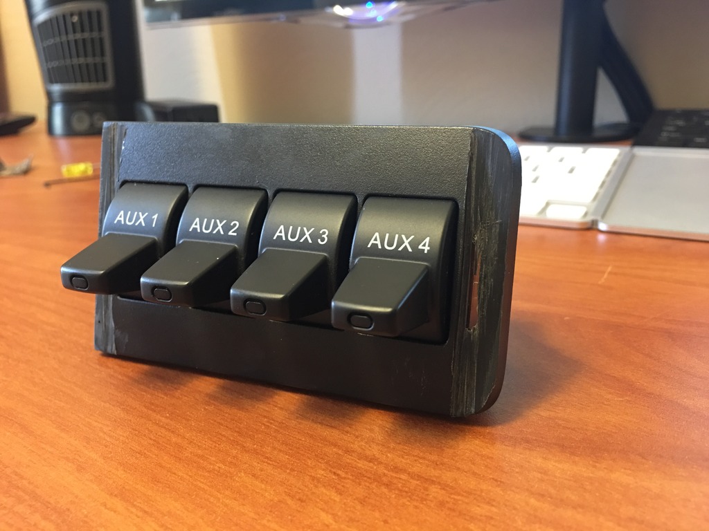
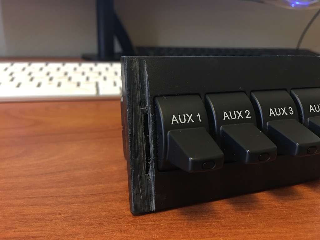
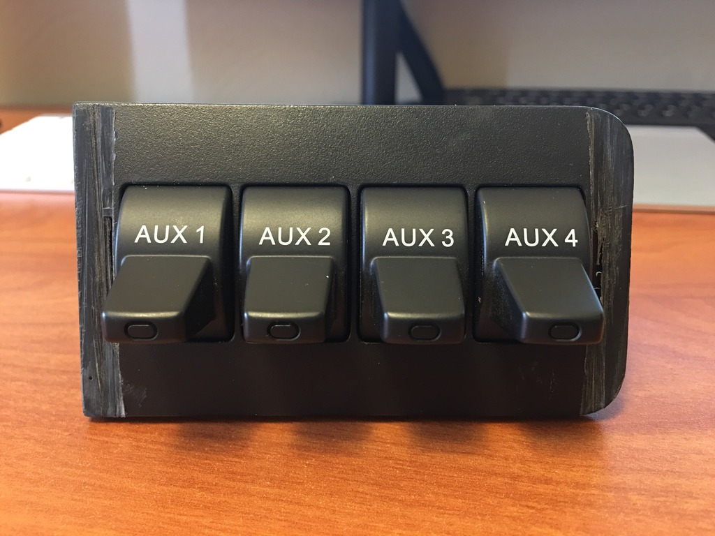
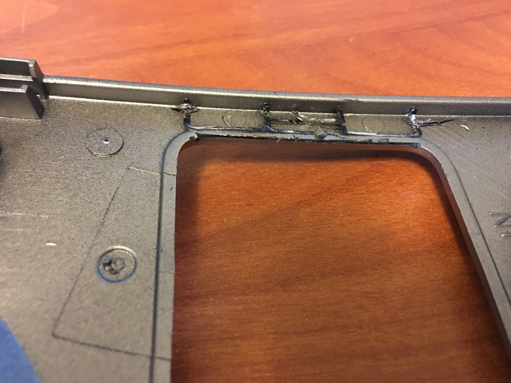
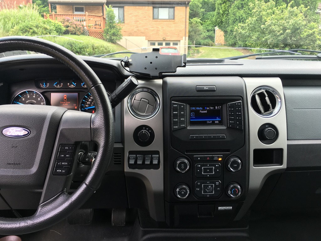
In the interest of moving this discussion along as well as show my progress, the actual switches have been mounted. In addition to the cutting and trimming I did to the edges, I also cut off the lip on the back side of the switch mounting plate. Unfortunately, I forgot to get pictures of that. I then JB Welded the hell out of the mounting plate to the dash panel. Here is the final product. I will get some photos of the JB Weld on the back side, whenever I pull the dash back off to complete the wiring.
I also wanted to size up the wiring from the plug at the switches to the relays. I have managed to remove the pins from the plug and am now on the search for new pins so I can build my own wiring. The pins measure out to about 2mm by 2mm square and about 8mm deep. Does anyone know where I might be able to find a pin connection like this? This can't be specific to Ford.
In the interest of moving this discussion along as well as show my progress, the actual switches have been mounted. In addition to the cutting and trimming I did to the edges, I also cut off the lip on the back side of the switch mounting plate. Unfortunately, I forgot to get pictures of that. I then JB Welded the hell out of the mounting plate to the dash panel. Here is the final product. I will get some photos of the JB Weld on the back side, whenever I pull the dash back off to complete the wiring.
07-05-2016, 07:01 PM
#4
Senior Member
Thread Starter
iTrader: (1)
I'll be hanging on to the brake controller for now. I don't tow much, but if I ever have a need for it, it can be thrown back in in about 10 minutes and another 5 minutes to turn it back on with FORScan. Of course, I'll probably need a new dash piece if I ever try to sell it with the brake controller. There is A LOT of JB Weld on the back of the panel now. Hahaha.
07-05-2016, 07:52 PM
#5
Senior Member
Thread Starter
iTrader: (1)
I was also able to finally pull the terminals from the upfitter relay pack. The terminal ends that Rigid used on their wires will not work. I tried. SO now I am on the hunt for these ends as well. Of course, if I can find the switch connector pins, I could easily just build my own relay pack. Again, any input at all would be greatly appreciated.
09-11-2016, 09:18 PM
#6
Senior Member
Thread Starter
iTrader: (1)
Alright. Doing more work on this install. Still working on it slowly. I was able to find the pins for the connector at the back of the switches. Found them completely by accident in the power fold mirror thread. The part number for the pins is 1719958-1.
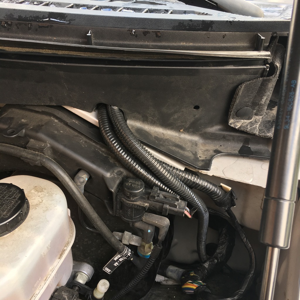
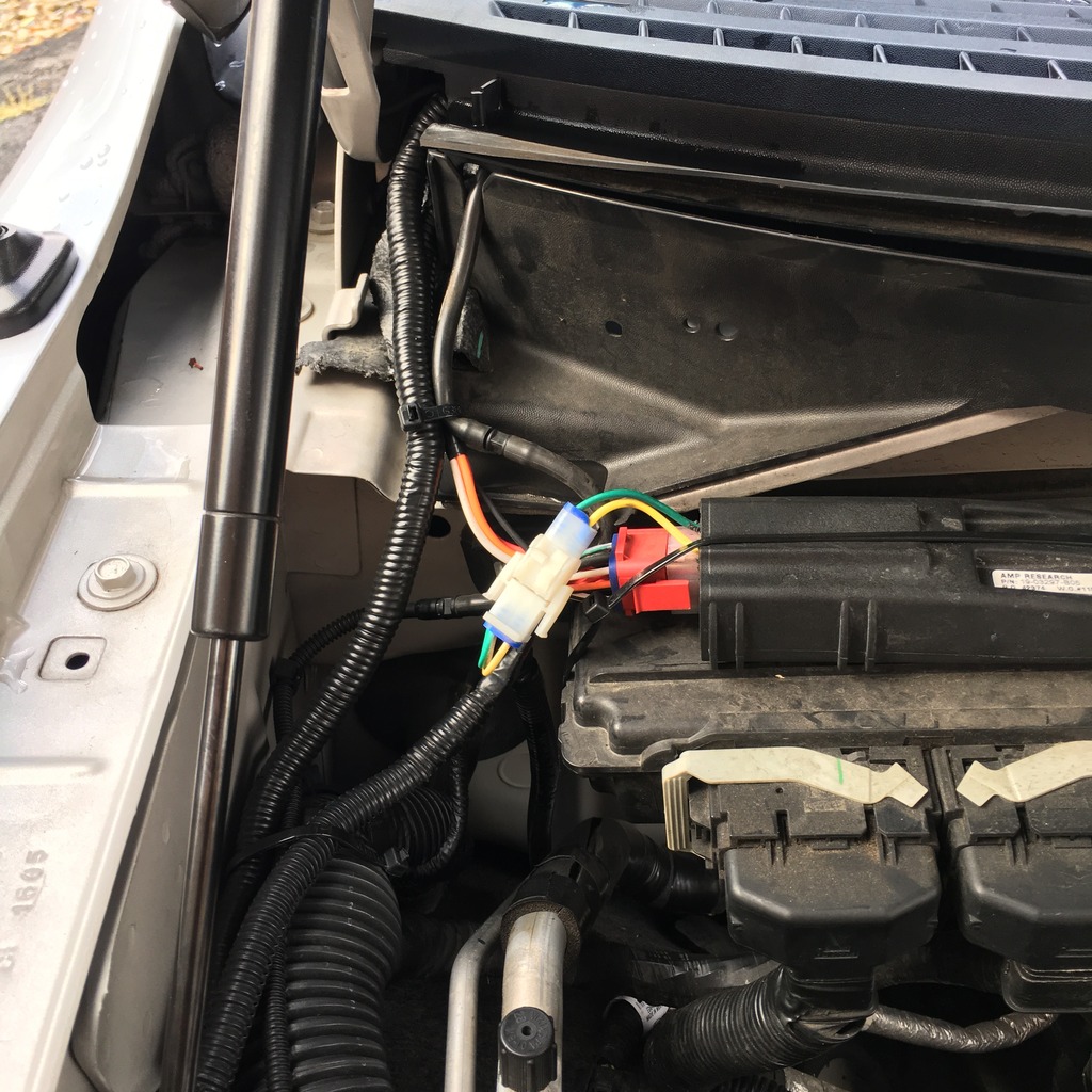
So I ran new 16-gauge wiring out to the aux fuse panel that Old Smoky made me. I ran the wires through the grommet in the firewall on the driver side.
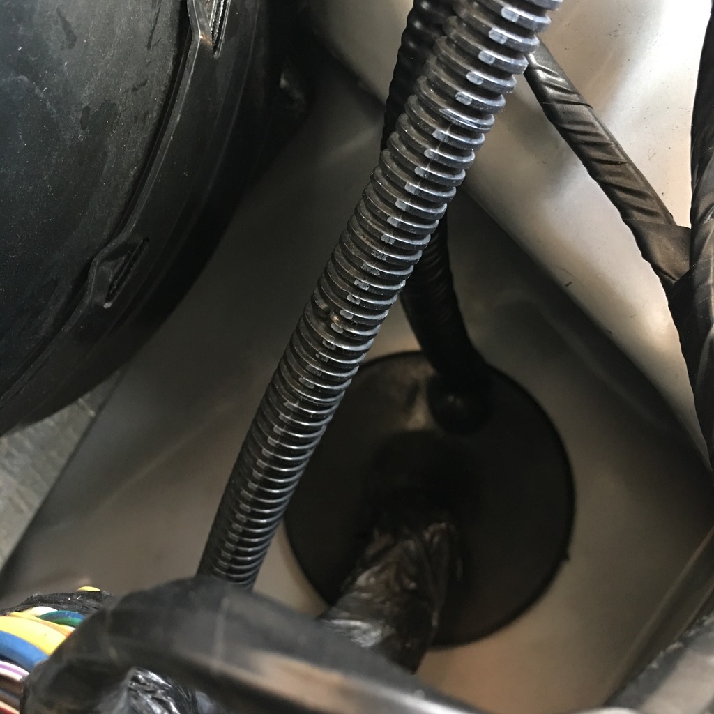
Then I ran the wiring up under the cowl with the amp power board wiring.
I then connected it all to the aux fuse panel that old Smoky made for me.
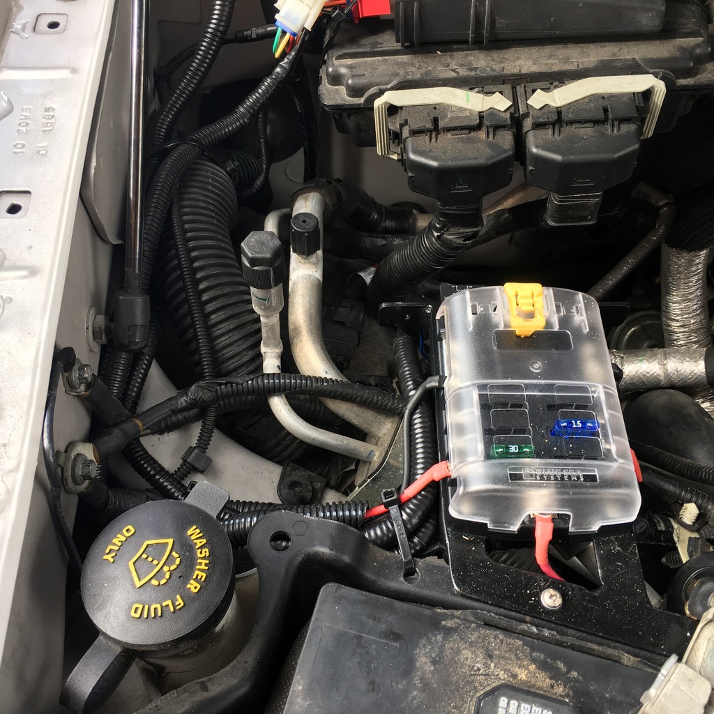
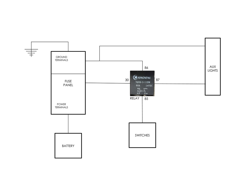
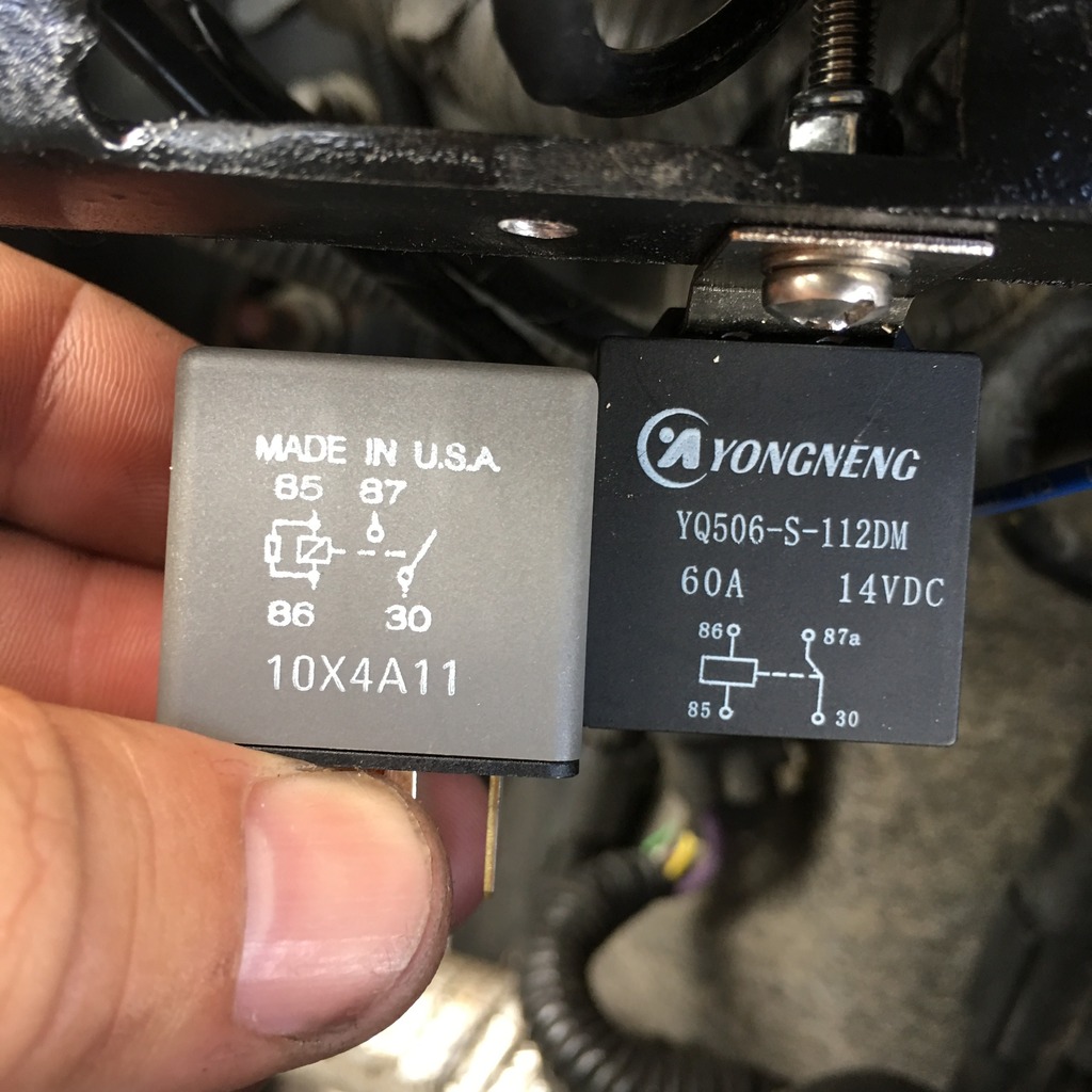
Now comes my question. I think I matched up the relay wiring to how the Ford switches work. I am using the relay that came with the Rigid lights though, not the Ford factory one. I have attached a diagram of how I have connected everything up. As well as a photo of the relay I am using (bolted to the fuse panel) and the Ford relay. Now my question is, did I wire the relay correctly or do I need to make some changes?
Thanks in advance for any help.
So I ran new 16-gauge wiring out to the aux fuse panel that Old Smoky made me. I ran the wires through the grommet in the firewall on the driver side.
Then I ran the wiring up under the cowl with the amp power board wiring.
I then connected it all to the aux fuse panel that old Smoky made for me.
Now comes my question. I think I matched up the relay wiring to how the Ford switches work. I am using the relay that came with the Rigid lights though, not the Ford factory one. I have attached a diagram of how I have connected everything up. As well as a photo of the relay I am using (bolted to the fuse panel) and the Ford relay. Now my question is, did I wire the relay correctly or do I need to make some changes?
Thanks in advance for any help.
Last edited by larryo108; 09-11-2016 at 09:21 PM.
01-23-2017, 01:10 PM
#7
Senior Member
+12v thru switches to relay coil. Other side of relay coil to ground. +12v from fuse panel to relay switch(pin 30). Other side of relay switch(pin 87) to light or other accessory. Your diagram is correct. 
Last edited by albi1cnobi1; 01-23-2017 at 01:11 PM. Reason: more info
Trending Topics
01-23-2017, 01:14 PM
#8
Senior Member
Thread Starter
iTrader: (1)
I was able to get the relay wired correctly and the switch is working with the aux lights in my bumper now. My only remaining issue at the moment is the illumination of the switches. I only get the yellow light when the switch is flipped on, but I have no illumination from the AUX1, AUX2, AUX3, and AUX4 lettering as there should be.
01-23-2017, 03:00 PM
#9
Senior Member
Pin #2 on the switch plug is violet/grey, thats the illumination wire. Run a wire to pin#1(violet/grey) at the dimmer switch. That'll get your switches lit up.