When you click on links to various merchants on this site and make a purchase, this can result in this site earning a commission. Affiliate programs and affiliations include, but are not limited to, the eBay Partner Network.
A light bar mount made from a futon haha ur a cheap *** idiot. Thank god , God made ppl like u so others can laugh.lol
My hat's off to him, and his futon light bar! this is America and free to try anything new, I once made an exhaust for a old Thunderbird out of an old bed headboard and it was the bad ***-est sounding,
had many compliments on its rumble.
Hi All I hope everyone is having a good Saturday, mine is not so good. I have a 1995 ford f150 with the 4.9 inline 6 with a 5 speed tranny that recently turned 400k . Not long after it turning 400k the rear end went out, so I am going to have to replace it. I saw a chart posted above and was wondering if it was correct, my door code showed a 17 on the axle and was wondering is there a difference with a v 6 and a inline 6. Right now I am trying to decide if it will be cheaper to replace the entire rear assembly or just the internals. Any thoughts on this would be appreciated.
I am doing new ball joints and and u joints and tie rod ends and i bought new tie rod ends just the outers and they are moogs and they won't fit into the adjusting sleeve they are way to small and just slide right into the sleeve any answers or recommendations
I am doing new ball joints and and u joints and tie rod ends and i bought new tie rod ends just the outers and they are moogs and they won't fit into the adjusting sleeve they are way to small and just slide right into the sleeve any answers or recommendations
Quick question for those who know, but what size of wheel spacers would you need to clear steering knuckles? Originally had level, so wheels won't clear after doing a suspension lift.Currently have 20x9 20mm offset and was wondering would 0.5" spacers clear it? Most lift kit's say you need 5"-5.5" back spacing. Mine is 5.79".
I love the hate Ray, keep wasting your time spewing your bull****, just do the world a favor, if you want to call someone an idiot, make sure your own reading comprehension skills are up to par. You also contradict yourself saying a truck isn't an investment, but then tell me to get rid of this and get a better truck.
This truck does the same as if I dropped $30k on a truck, it suits my needs, will pay for itself soon enough, and contrary to your belief, I could turn around and sell it and make money. I've lost money on one car out of the 12+ I've owned, so I have a clue.
And I hope you enjoyed fluffing your feathers calling me cheap and whatever other jibberish you typed out, because at the end of the day, it's my choice so I can get more money into the bank and investments. I could buy a Raptor with cash if I wanted to, except I won't because I'm not a fool like you and don't have to prove my self worth on the road.
I dont no why I keep coming back here. O yeah I'm not a mechanic! But I am a man! If you where face to face with me you wouldnt be talking to me that way! And I'm sure of that!! Why are these people allowed to continue to insult people on this forum?????
Step 1 - Carefully pop the switch off of the cover. There's 2 clips on each side.
Step 2 - Pop the rocker off of the switch. (next picture shows what it looks like off)
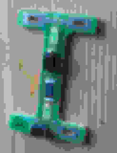
Step 4 - Now you can see the board with the lights:
Step 5 - You can see these contacts SOMETIMES come loose (as mentioned earlier). You can sometimes add solder and this will fix the problem but CHECK the resistor first or this will be difficult to remove later.
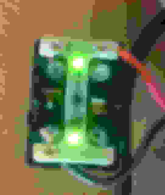
Step 6 - you can test by applying 12 volts to the pins below. ****** NOTE - Where it says "2" is actually the positive!!!! The ground is below. The picture is deceiving as it was hard for me to get the wires to hold. If you do this test and you get no lights, try moving the board, twisting it, if you can get your hand on the resistor apply slight pressure to it. If you see the lights come on, there's the problem.
Step 7 - Remove the rocker plastic piece. Notice, it'll have an extra notch on the one side (you'll see what I mean when you put it back together).
***** This is a good time to clean the contacts!
Step 8 - Use pliers to bend the contacts in (so you can take the board off)
*** I just realized I didn't add a picture of how to remove the actual board. Use the pliers open end and lift on the outer corner of the board to avoid adding damage. If you want a picture let me know and I'll add one .
Step 9 - Alright, here's likely the problem. The resistor circled below comes loose. Be VERY careful when soldering it back on, it'll probably attach to the soldering iron. Use a Q-Tip or something to hold it if you can. *** Note: I believe what happens here is the resistor gets so hot with a weak soldering job that it actually separates from the board. One of mine literally fell right off.
Step 10 - Do another test before putting it all back together:
Important to note again, the side of the circuit board that says "2" is the positive for testing.
- Assembly is the reverse . Careful putting the board back on. I soldered mine on anyways to be extra safe.


 04-04-2019, 09:34 PM


 .
.