
Stereo Build in 2013 Ford F150 FX4
 03-11-2014, 02:08 AM
#51


So I'm getting close to purchasing everything for the install.
I downloaded the manuals for both amps and the LC8i (If I want to add another device, ect...I have the option with this).
Can someone with experience tell me what size speaker wire the Audio Control Interface will take? The manual doesn't provide that answer.
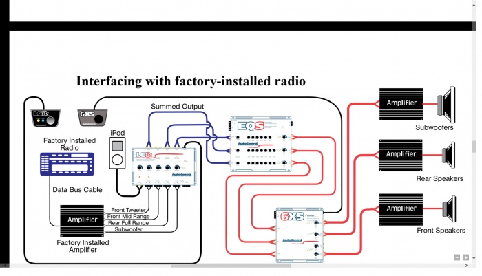
Here's a wiring diagram from the manual:

Also, for anyone who also will be tapping into the factory wiring at the sony amp, what gauge wiring are or did you run off the tap? 12, 14, or 16 gauge? I'm asking because I'm ordering 75 ft of nvx 12 gauge and if I have some available, I'll just use that.
All thoughts, comments, suggestions are welcome!
I downloaded the manuals for both amps and the LC8i (If I want to add another device, ect...I have the option with this).
Can someone with experience tell me what size speaker wire the Audio Control Interface will take? The manual doesn't provide that answer.
Here's a wiring diagram from the manual:
Also, for anyone who also will be tapping into the factory wiring at the sony amp, what gauge wiring are or did you run off the tap? 12, 14, or 16 gauge? I'm asking because I'm ordering 75 ft of nvx 12 gauge and if I have some available, I'll just use that.
All thoughts, comments, suggestions are welcome!
 03-11-2014, 07:25 AM
#52
03-15-2014, 03:10 AM
#53
All of my equipment & accessories have been ordered! 
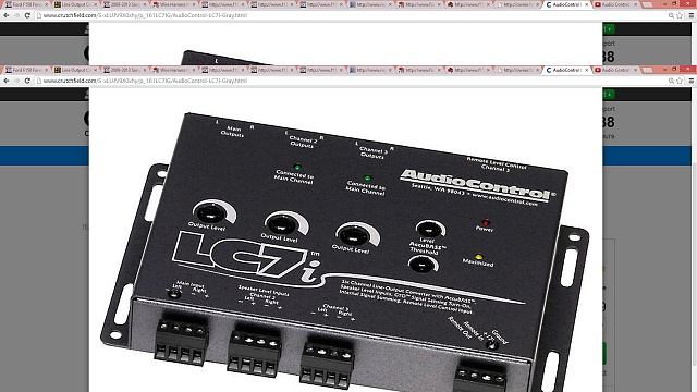
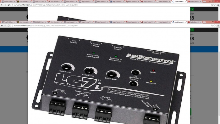
I decided to go with the Audio Control LC7I for a processor.
I found a very informative video on the product:
A lot of you guys have really helped a tremendous amount through my learning process. So if you could once again....provide clarity on wiring the factory input wires to the LC7i.
The video posted at (2:10-2:15) states that the processor provides two input channels and 3 output channels. I'm assuming the inputs, in my case, are the factory speaker wire I'm tapping into. If that's the case, then can someone help me understand how I can run all: Front driver/passenger mids and tweeters, rear driver/passenger speakers, and dual voice coil sub wires all run into the processor?
Here is how I'm thinking the wiring should be:
Speaker wire detail
Center Front Speaker on Dash (+) Green, (-) Gray/Yellow
Driver Front Speaker (+) White, (-) White/Brown
Driver Front Tweeter (+) Green/Orange, (-) Gray/Orange
Passenger Front Speaker (+) White/Purple, (-) White/Orange
Passenger Front Tweeter (+) Purple/Orange, (-) Yellow/Orange
Driver Rear Door (+) White/Green, (-) Brown/Yellow
Passenger Rear Door (+) Brown/White, (-) Brown/Blue
Sub Dual Voice Coil
1) (+) Purple/Green, (-) Green/White
2) (+) Green/Purple, (-) Gray
The Main Input:
Left:
Combine the Front Driver side speaker (+) White, (-) White/Brown with the Front Driver side Tweeter (+) Green/Orange, (-) Gray/Orange
Right:
Combine the Front Passenger side speaker (+) White/Purple, (-) White/Orange with the Front Driver side Tweeter (+) Purple/Orange, (-) Yellow/Orange
Channel 2:
Left:
Rear Driver side speaker (+) White/Green, (-) Brown/Yellow
Right:
Rear Passenger side speaker (+) Brown/White, (-) Brown/Blue
Channel 3:
Left:
Sub voice coil #1 (+) Purple/Green, (-) Green/White
Right:
Sub voice coil #2 (+) Green/Purple, (-) Gray
Is this an accurate setup?
Would the video around (2:59-3:36) where switching the jumpers to sum
is discussed be something that I should do? Or am I confusing myself?
Hopefully all this information helps someone other than myself!
03-16-2014, 01:37 AM
#54
Started doing a little bit prep work for the system install.
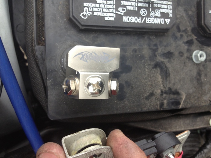
Today, I received my new battery terminals, wiring, distribution blocks, ring terminals, solder, fuses (200 amp) & fuse blocks. I got excited and went under the hood to see how the battery terminals would look. It looks good, but after a couple of minutes I realized that I had a problem.
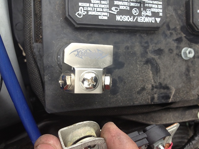
The problem is the factory wiring that was originally connected to the battery. (It wouldn't work with my new terminal)
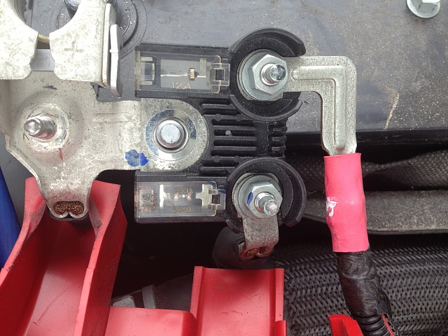
No problem....just another project within the project.
I decided to create a custom bracket so that I could keep all the factory wiring hooked up, and still be able to utilize my new terminal.
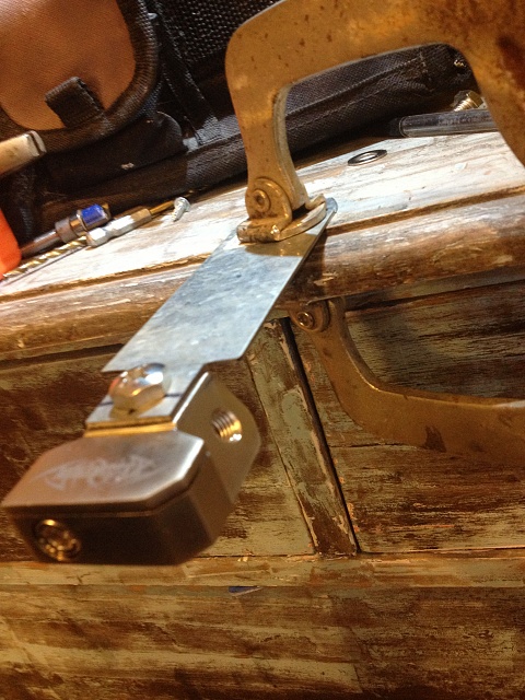
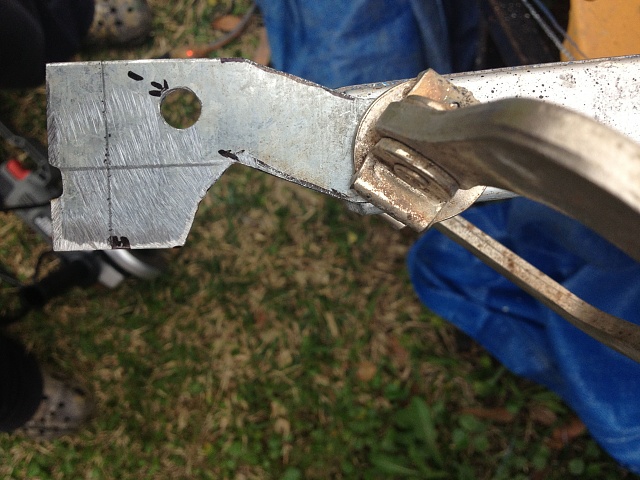
Bracket taking shape
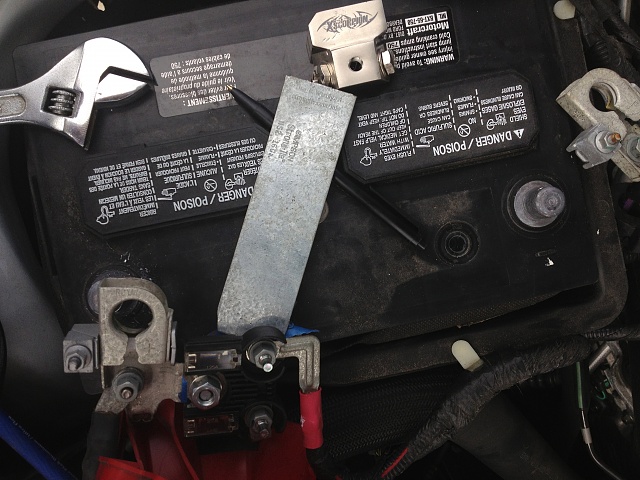
The finished product

Today, I received my new battery terminals, wiring, distribution blocks, ring terminals, solder, fuses (200 amp) & fuse blocks. I got excited and went under the hood to see how the battery terminals would look. It looks good, but after a couple of minutes I realized that I had a problem.
The problem is the factory wiring that was originally connected to the battery. (It wouldn't work with my new terminal)

No problem....just another project within the project.
I decided to create a custom bracket so that I could keep all the factory wiring hooked up, and still be able to utilize my new terminal.

Bracket taking shape


The finished product
 03-16-2014, 06:29 PM
#55
So, I've got my terminals squared away. I started looking at around in the engine to run a new power wire to the alternator.
Has anyone run new 0 gauge wire to the alternator?? You've got a lot to take out before you can actually access the backside.
If there is an easier way, maybe coming in from the bottom of the vehicle rather than the top?
Has anyone run new 0 gauge wire to the alternator?? You've got a lot to take out before you can actually access the backside.
If there is an easier way, maybe coming in from the bottom of the vehicle rather than the top?
03-16-2014, 09:42 PM
#56
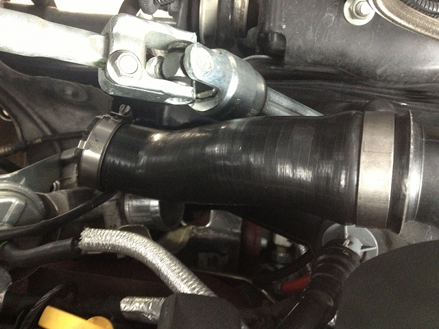
I made an attempt to get to the alternator, which is located below the drivers side valve cover. In addition, all of the air intake connectors leading to turbo are all in the way.
I made an attempt to remove all the tubing, but I ran out daylight and had to put it all back together for work tomorrow.
Here are few pictures I took:
The red wire way in there is where I need to get
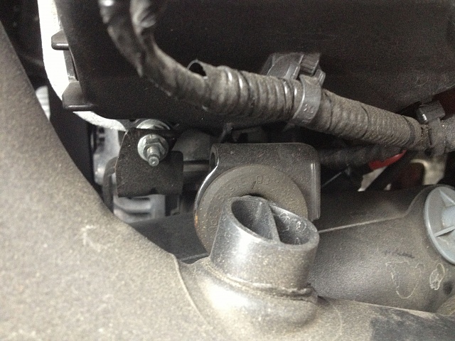
View closer up
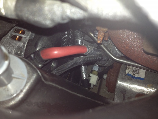
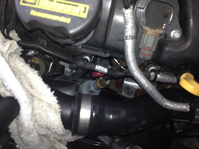
Until changing this wire is a must...I'm holding off
I made an attempt to remove all the tubing, but I ran out daylight and had to put it all back together for work tomorrow.
Here are few pictures I took:
The red wire way in there is where I need to get


View closer up


Until changing this wire is a must...I'm holding off


 03-18-2014, 12:14 AM
#58
Anyone ever come across this guys videos on youtube? He connects to the factory wiring at the amp in the center console with no splice or tap. He basically explains what he's doing in four (4) videos.
Check out his videos:
1
2
3
4
I'm no expert at any of the stuff. I'm hoping someone will come across my posts and help me comprehend how to do this. Need help from the Experts!!
Check out his videos:
1
2
3
4
I'm no expert at any of the stuff. I'm hoping someone will come across my posts and help me comprehend how to do this. Need help from the Experts!!
