

Build Thread- Supercab FX4 5.4L

Heres my audio build thread.
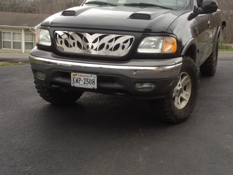
Truck-03 Supercab FX4 5.4 L with 305-70-17 MTR Kevlars
Painted Calipers
Big-3
Dual straight pipes(no cats)
CAI
Switchblade Grill
Hood scoops
and many more
Audio upgrades
Big 3(All 1 ga. mining wire) (350 amp fused wire to amp d-block)
All amp wires and dblocks (1ga mining wire)-250amp fuse and 100 amp fuse
HU- Alpine CDA 7894, KCA 420i, C701 Processor
Front- 6.5 Focal K2 Powers
Rear- 6x8 Alpine R's
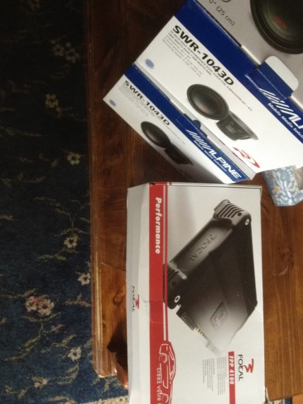
Subs- 2x Full size 10" Type R's
Amps- Focal FFP 4100(95x4 at 4)
Amp - Rockford Power Series T1500-1bdCP (1932 rms at 1)
Custom Enclosed Under seat box - 2 Type R's with approx .74ft^3 per sub
Custom Amp Rack
Custom Rear seat(refabbed)
Here is what I am working on


Headunit and Options
Alpine CDA 7894 (AMAZING SQ and Options) also the green matches the 03's factory lighting. 3 -4V preouts
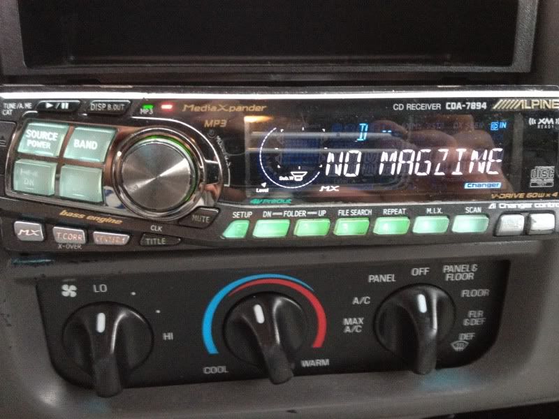
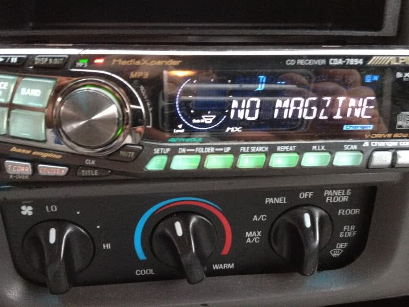
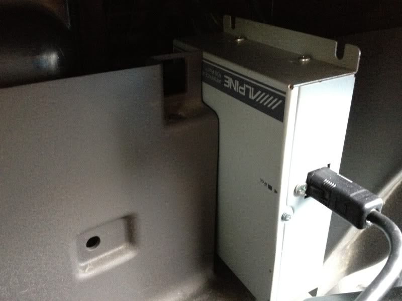
KCA 420 for Iphone's and Ipods
For the Box
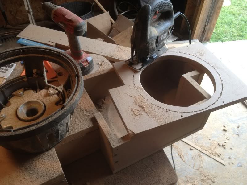
Start of the design.
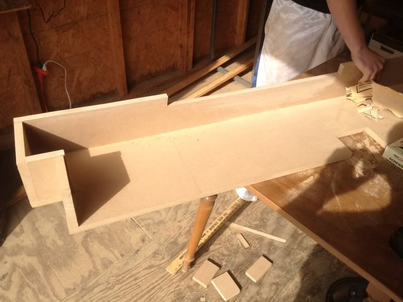
Here's when I finished the frame and internals of the two 10" type R's box
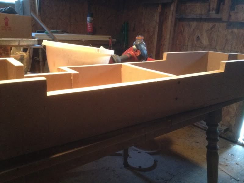
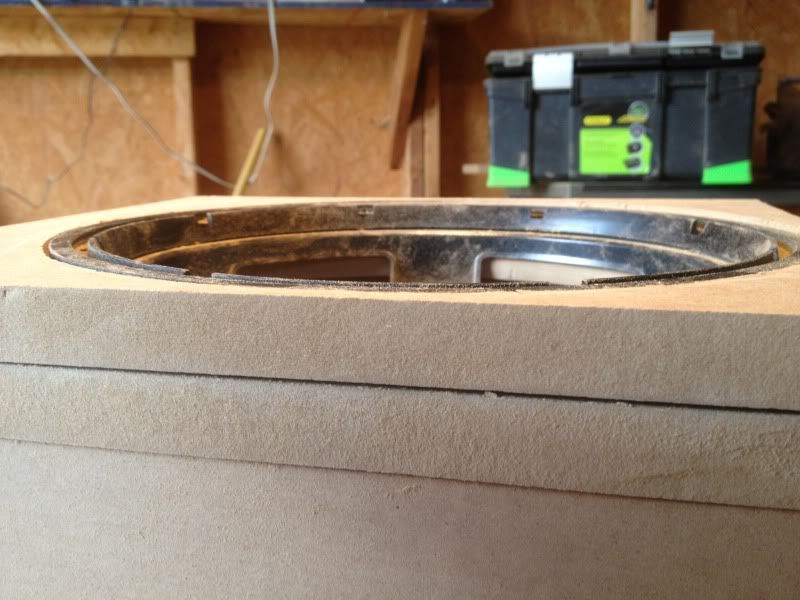
Notice the down firing spec. By going that route I had about 5.875 top mounting depth.
Also note how I countersinked them about 1/4 ito the MDF to help with some depth
Truck-03 Supercab FX4 5.4 L with 305-70-17 MTR Kevlars
Painted Calipers
Big-3
Dual straight pipes(no cats)
CAI
Switchblade Grill
Hood scoops
and many more
Audio upgrades
Big 3(All 1 ga. mining wire) (350 amp fused wire to amp d-block)
All amp wires and dblocks (1ga mining wire)-250amp fuse and 100 amp fuse
HU- Alpine CDA 7894, KCA 420i, C701 Processor
Front- 6.5 Focal K2 Powers
Rear- 6x8 Alpine R's
Subs- 2x Full size 10" Type R's
Amps- Focal FFP 4100(95x4 at 4)
Amp - Rockford Power Series T1500-1bdCP (1932 rms at 1)
Custom Enclosed Under seat box - 2 Type R's with approx .74ft^3 per sub
Custom Amp Rack
Custom Rear seat(refabbed)
Here is what I am working on
Headunit and Options
Alpine CDA 7894 (AMAZING SQ and Options) also the green matches the 03's factory lighting. 3 -4V preouts
KCA 420 for Iphone's and Ipods
For the Box
Start of the design.
Here's when I finished the frame and internals of the two 10" type R's box
Notice the down firing spec. By going that route I had about 5.875 top mounting depth.
Also note how I countersinked them about 1/4 ito the MDF to help with some depth
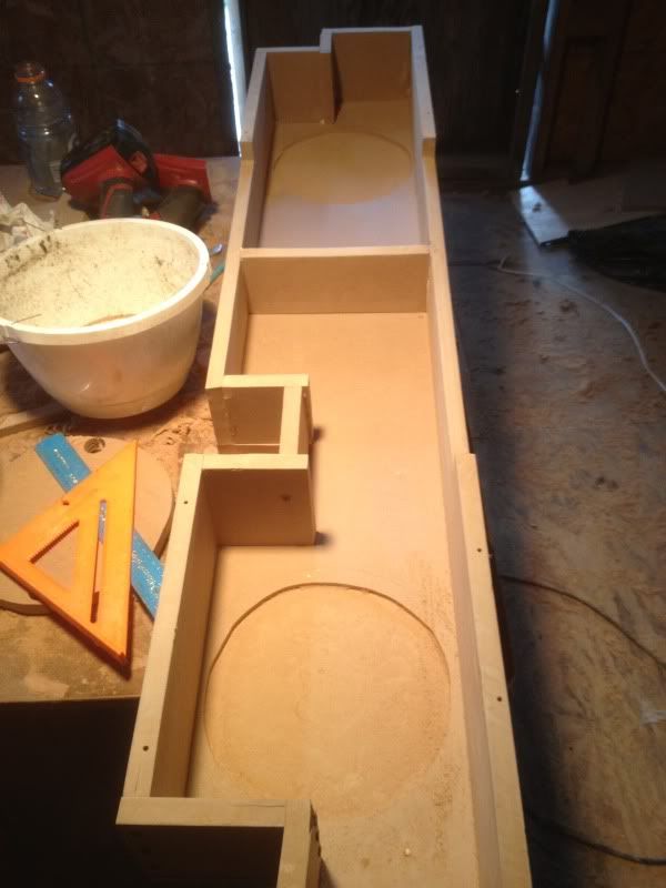
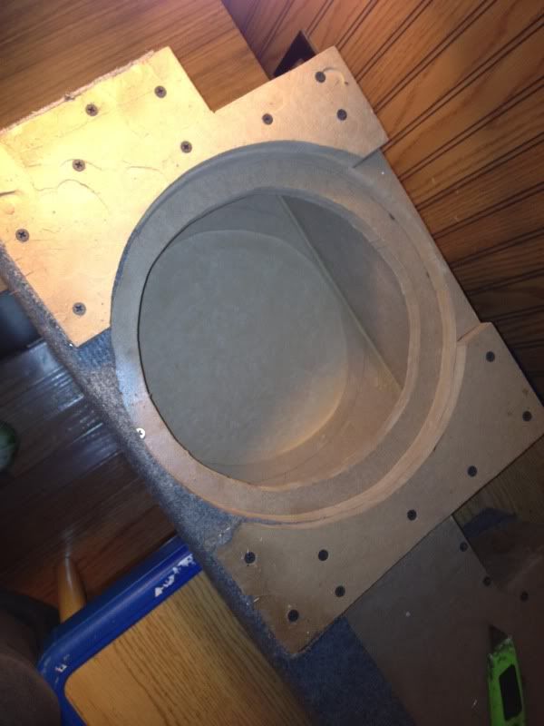
I used an old Type R I blew as a guide to go by. Also helped out with making the proper baffle
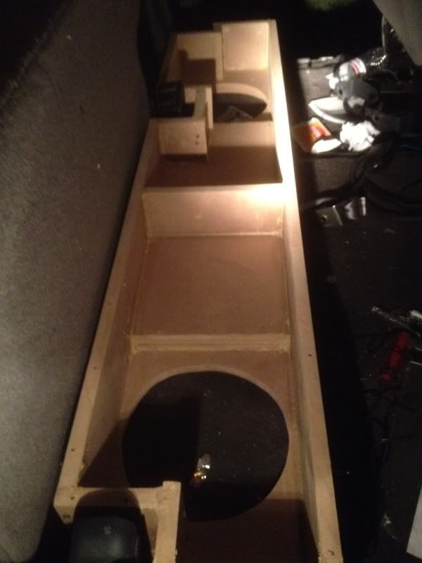
Heres the double baffle which will serve as a mounting place for the legs to lift the box to give room for excursion of about 20mm.
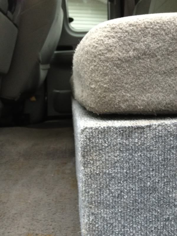
Heres the ("legs") on top of the baffle to give room for the Xmax
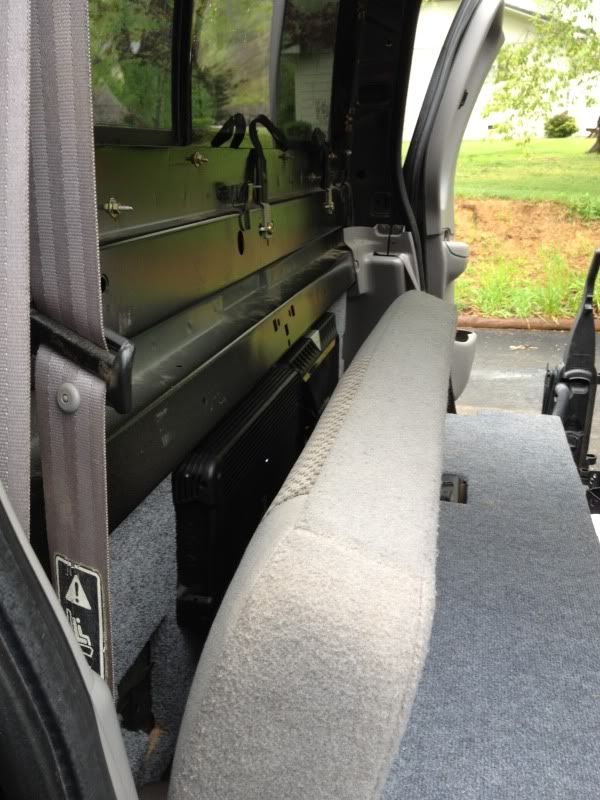
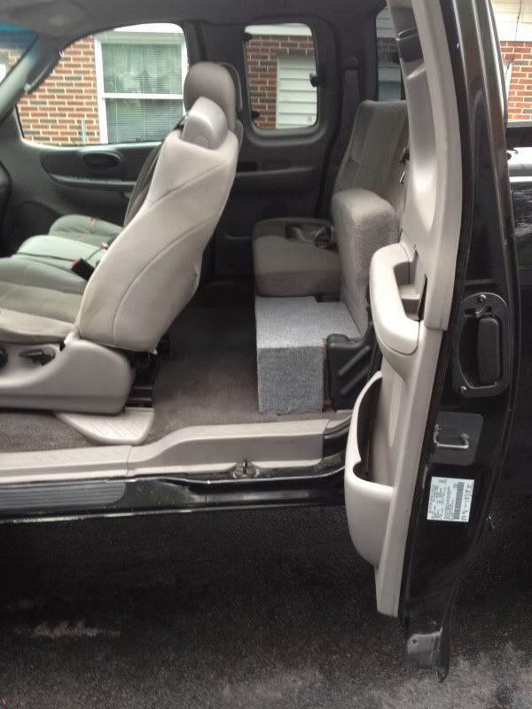
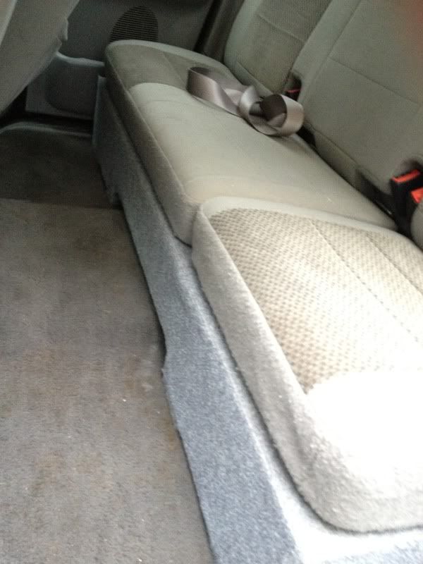
With carpet on it fitting into the back seat slots.

Legs holding it up to breathe and not hit the floor
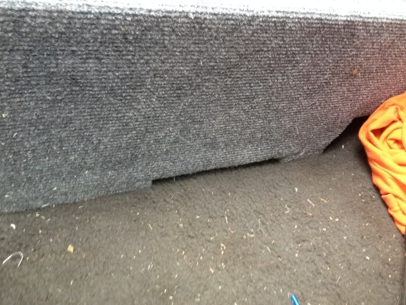
Notice how flush it is to the rear seat(11.25inches)
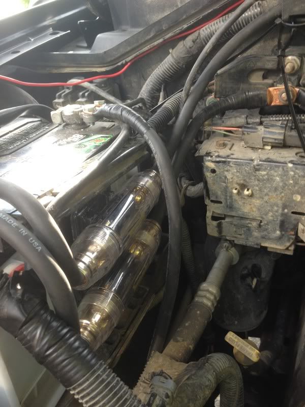
Next I upgrades the "big 3" with 1ga mining wire. Then ran the same wire to my dist block for the amps.
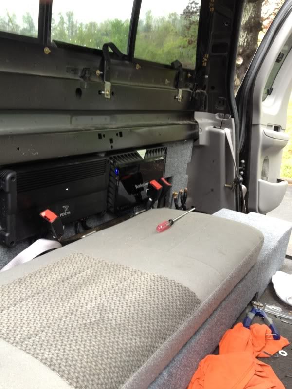
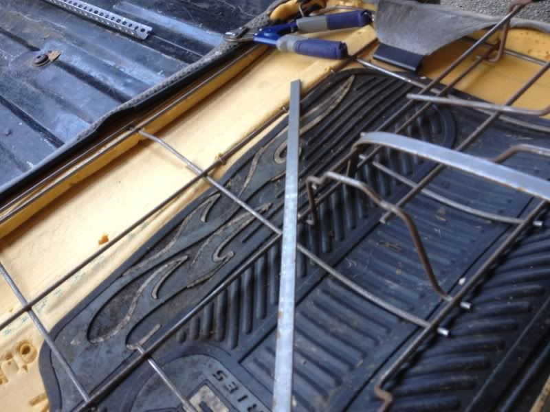
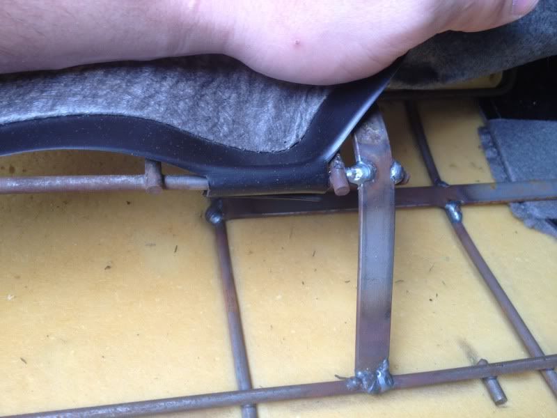
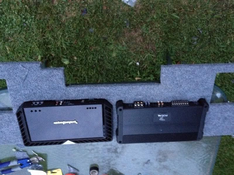
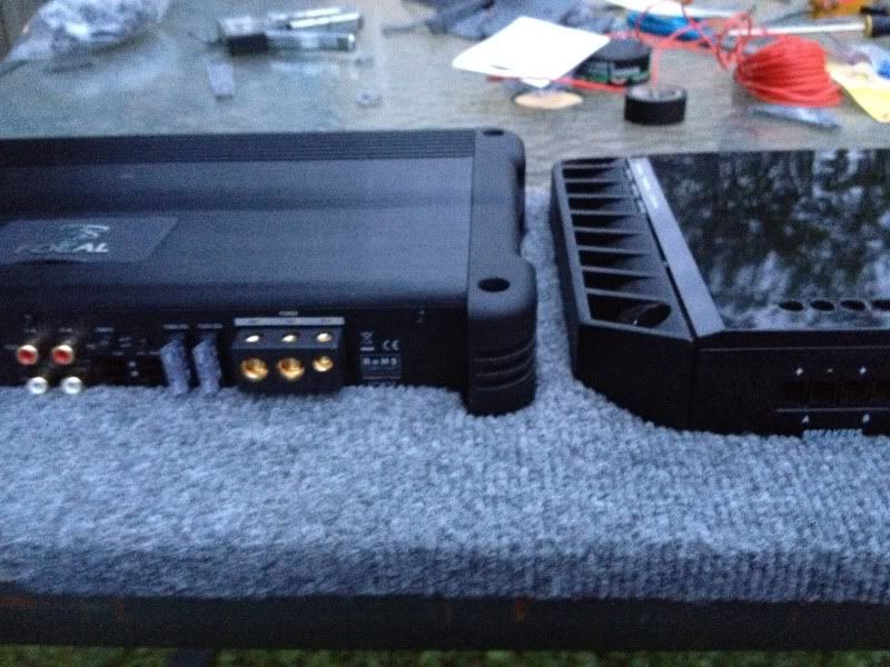
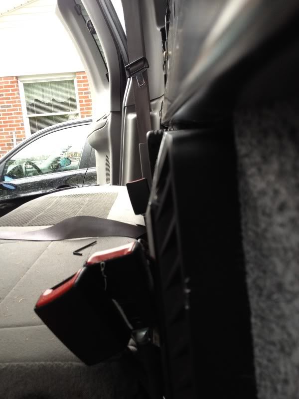
Now for the back seat amp rack since I got these in:
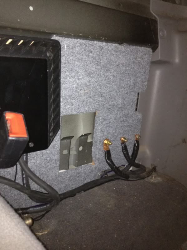
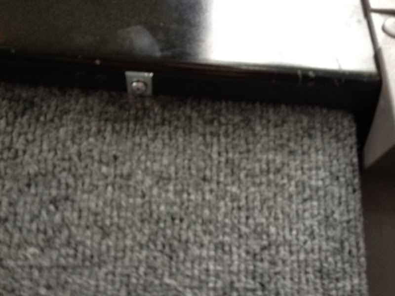
Notice the two brackets holding the back seat to the cabin. I had to refab this part to make room for the amp rack. Heres a shot of what I am talking about
Heres the double baffle which will serve as a mounting place for the legs to lift the box to give room for excursion of about 20mm.
Heres the ("legs") on top of the baffle to give room for the Xmax
With carpet on it fitting into the back seat slots.
Legs holding it up to breathe and not hit the floor
Notice how flush it is to the rear seat(11.25inches)
Next I upgrades the "big 3" with 1ga mining wire. Then ran the same wire to my dist block for the amps.
Now for the back seat amp rack since I got these in:
Notice the two brackets holding the back seat to the cabin. I had to refab this part to make room for the amp rack. Heres a shot of what I am talking about
Now to the welding and bracing part for the back seat frame.
Obviously this requires a welder, heres the one I used.
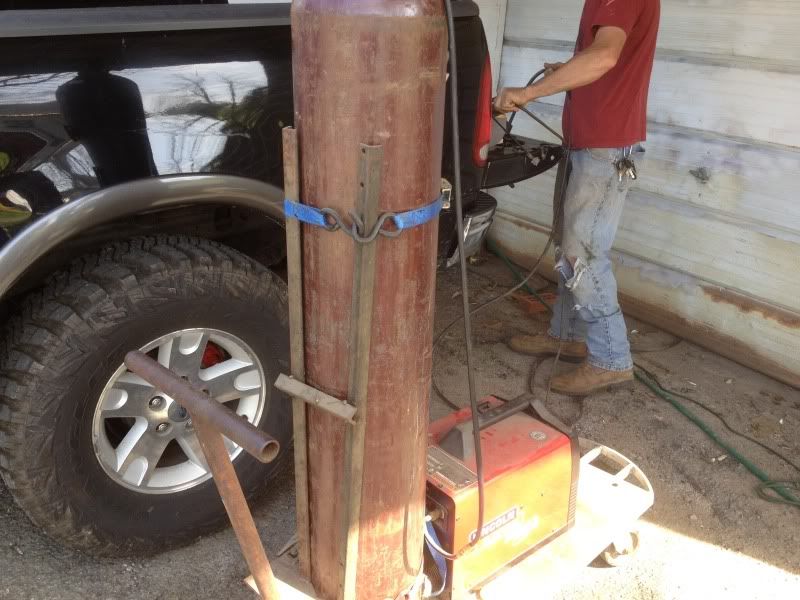
I had to cut some of the old framing for the back seat off to make room for two 15inch wide amps. Once I cut the excess of I re-welded some steel rods for support(two places where the back seat is held to the cab)
Once I made room it was time to fab the MDF amp itself.
Here is a few shots of the amps being couternsinked into the MDF to leave room for the seats
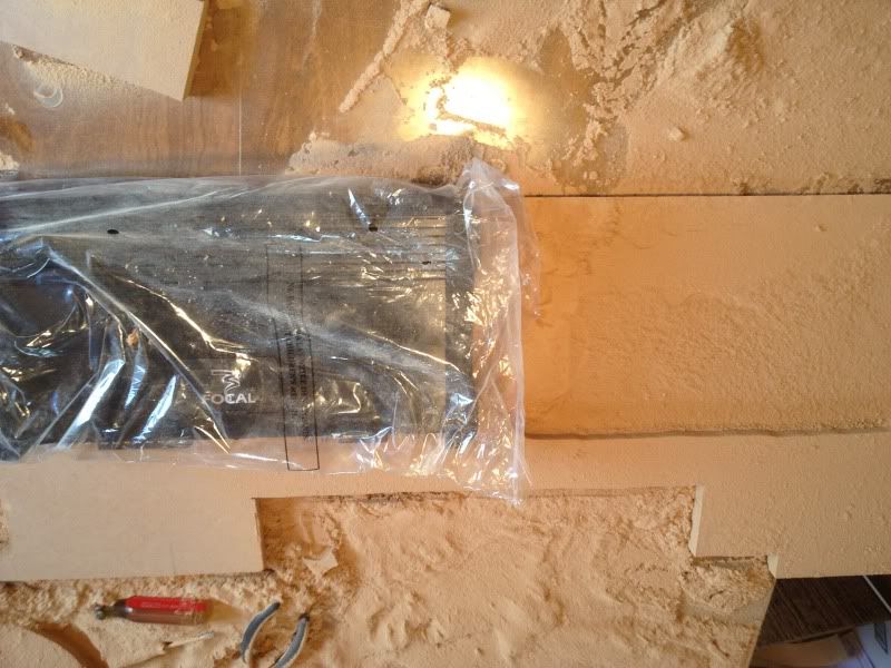

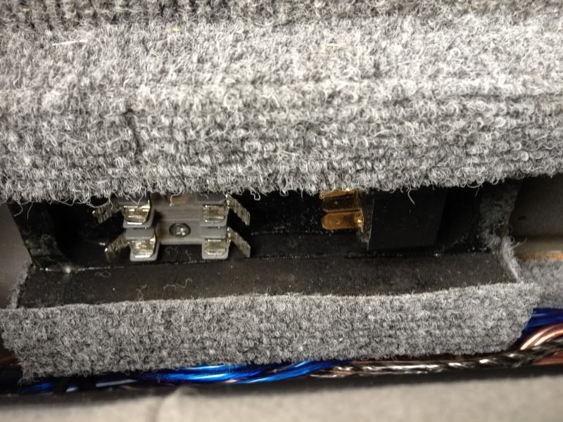
I also used the amp rack to hold some bolts for a distribution block. I hate paying crazy amounts for stupid fuse blocks and dblocks when you can make one this simple. I used a copper bar on the rear countersinked(covered with plexiglass) to attach a 250, and 100 amp fuses. This was all done with 1ga mining wire.
Obviously this requires a welder, heres the one I used.
I had to cut some of the old framing for the back seat off to make room for two 15inch wide amps. Once I cut the excess of I re-welded some steel rods for support(two places where the back seat is held to the cab)
Once I made room it was time to fab the MDF amp itself.
Here is a few shots of the amps being couternsinked into the MDF to leave room for the seats
I also used the amp rack to hold some bolts for a distribution block. I hate paying crazy amounts for stupid fuse blocks and dblocks when you can make one this simple. I used a copper bar on the rear countersinked(covered with plexiglass) to attach a 250, and 100 amp fuses. This was all done with 1ga mining wire.
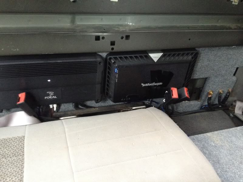
Heres a few shots with the amps in place
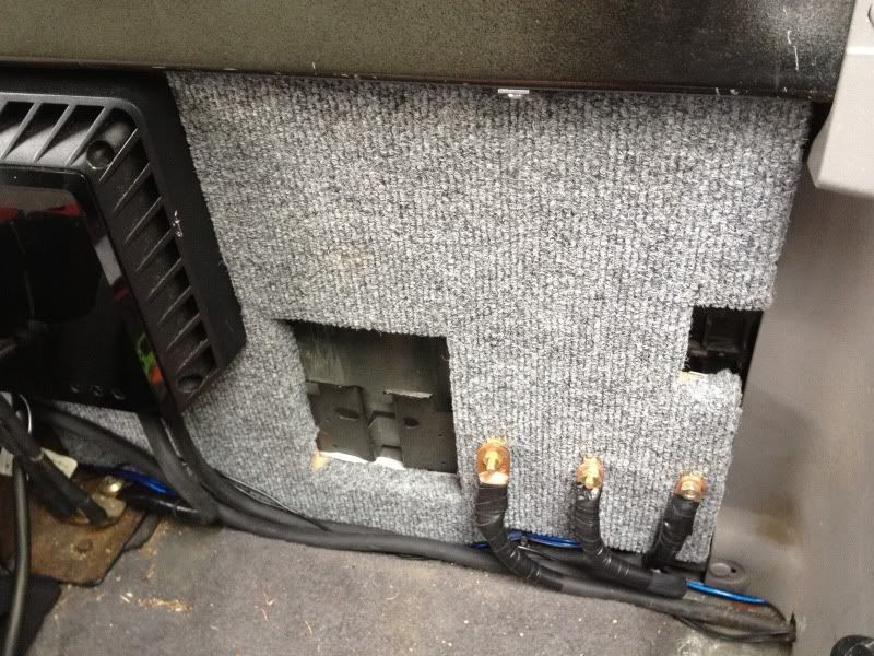

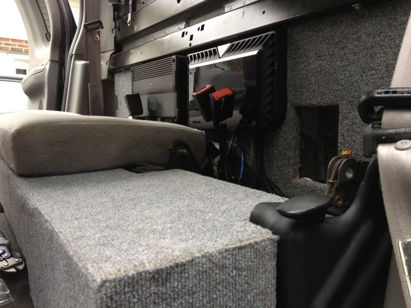
I didnt have much room to work with
Made a built in slot to hold relays, and fuses for; Fans, Heatsink Fans, and a better Remote signal(this has a sliding place for a piece of plexiglass)
More relays and switches hid to run 30amp for lights and 4" Vent fans.
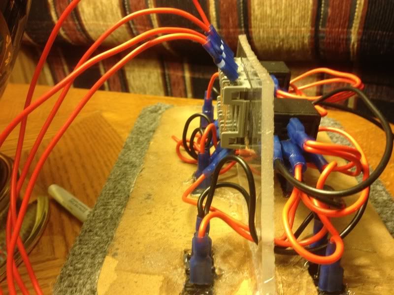
I used L brackets to mount it to the stabilizing bar for the cab
I didnt have much room to work with
Made a built in slot to hold relays, and fuses for; Fans, Heatsink Fans, and a better Remote signal(this has a sliding place for a piece of plexiglass)
More relays and switches hid to run 30amp for lights and 4" Vent fans.
I used L brackets to mount it to the stabilizing bar for the cab
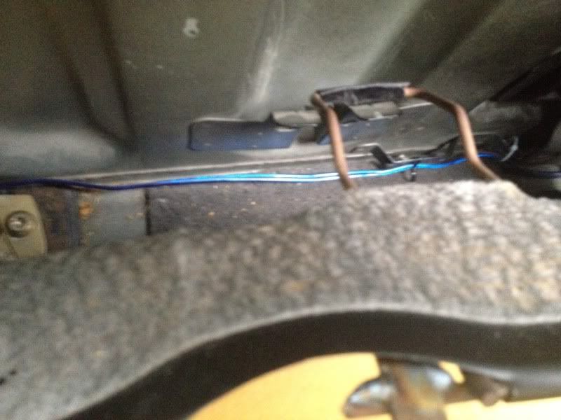
The other day I was trying to hook up my 16ft trailer to haul some wood off, however, the lights on the trailer refused to work. Got out the DMM and check the fuses, relays, and wires. Then sure enough, found the issue; insulation was broke on 3 of the 7 wires, and the left + right turn wires had obviously hit the chassis. This pretty much burned the insulation and they eventually disconnected themselves form the 7 pin plug. So I re-ran all new wires, (12ga to power, ground, aux, and brake, then 16ga to turn and running lights) then upgraded to a better Hopkins 7 pin to match the color of my lower valance.
I also took the bracket off(only held on by a 13mm bolt) and rhino lined it for a better look and rust resistance.


Now that I fixed the wiring up, I got ambitious and decided to "black out" my markers and signals to match the black. Used some 800, 1500 and 2000 grit sandpaper to wet sand the signals. I taped off the back up lights, for obvious reasons.


Then I got a little tirgger happy with the rattle cans and decided to black out the 330i's side makers. Which I was very pleased with.
Before: you can see the dull clear side markers.

After: sorry its super dirty.

I'll post more pics of the nightshade tint in a reply..
I also took the bracket off(only held on by a 13mm bolt) and rhino lined it for a better look and rust resistance.
Now that I fixed the wiring up, I got ambitious and decided to "black out" my markers and signals to match the black. Used some 800, 1500 and 2000 grit sandpaper to wet sand the signals. I taped off the back up lights, for obvious reasons.
Then I got a little tirgger happy with the rattle cans and decided to black out the 330i's side makers. Which I was very pleased with.
Before: you can see the dull clear side markers.
After: sorry its super dirty.
I'll post more pics of the nightshade tint in a reply..
Then I decided to go a little darker and still keep my back up lights clear. I left the tap on to add additional clear coats(if necessary).


Once I got the glossy look I wanted, I took the tape off.

Once I got the glossy look I wanted, I took the tape off.
Trending Topics

Love the mtr's. Had the mud grapplers before these and I can't even compare how much better they are for all around traction.
One amp is a 4 channel. That goes to the 4 door speakers
The other amp is to two subwoofers.
There are lots of options, but I wanted power and SQ so I chose focal and Rockford. They just suck up alot of current
One amp is a 4 channel. That goes to the 4 door speakers
The other amp is to two subwoofers.
There are lots of options, but I wanted power and SQ so I chose focal and Rockford. They just suck up alot of current
Second battery Install. Plus relocating washer fluid tank.
I know alot of us members have quite a few electrical components running off factory wiring and our factory alternator. Hid's, Amps, Winches, Aftermarket HU's, Off Road Lights, Power inverters, CB's, etc.
Hence, I thought it could be very useful to find a place to install an extra battery for reserve power or to integrate into the factory system. This would require a few modifications;
First, under our hood there is little to now room. So modifications had to be made and something had to be moved to another location. Almost all batteries need to be close to level for optimal efficiency and lifespan. Plus, what better place to protect a battery, than under the hood. (I didn't want the battery taking space up in the cab)
Second, I wanted to make the 2nd battery strictly for Starting and running critical applications(fuel pumps, winches, starter, ignition system).
Third, I was debating on whether or not to have the alt continuously charge the 2nd battery. Then decided to go ahead and use a battery Isolator to charge both the batteries simultaneously, but separate them when the vehicle is off.
Once all that was contemplated about, I needed to find out the usage of all my components and the stress it would put on my alternator. Hence, I've been trying to find some info on the amps of our factory alt. but have yet to find a reliable source, so I would assume its in the range of 100-130 amps.
Mathematically, this would mean; (this is running at full capacity)
note: anything over, and your alt. will be unable to run your components and effective charge your batteries. The alt. needs to be somewhat > than the power you are pulling. Alts. are rated mainly at max ouput and not at idle. So consider this when doing your install and choosing an alt.
Here are the specs I calculated;
Amps = Watts / Volts
For a 100 amp Alt, you could get approx.
1440.000000 watts
For a 130 amp Alt, you could get approx.
1872.000000
And a 180 aftermarket alt.
2592.000000
So I decided to go ahead and do the second battery and change to a 180 alt. I also wanted to upgrade the factory 4ga and 6ga wire to a better, thicker conductor. I went with 1ga mining cable, (it was a little bit of over kill) but being in a mining community I get it fairly cheap. ($1.50 per foot). Holds upwards around 500amps and 600 volts. 30ft of it weighed in about 35lbs. I also decided to upgrade all wiring that charges, starts, and runs the truck.
Now for wiring the starter with better wire.
DISCONNECT YOUR BATTERY FIRST****
You only need to upgrade the 12v supply and the ground. The other smaller red wire, is the ignition lead.
Note: power is always running to the starter, however, the starter solenoid only engages when the ignition is turned on. Due to the harsh winters here, I wanted to have amps running from both the batteries to starter. There are many ways to wire this up, but this is my method and how it benefited my application.
I used an extra starter relay, to only engage the second battery when the ignition is turned over. Thus it isolates the 12v supply from each respective battery when the ignition is not engaged(for starting). Once the truck is cranked, the batteries separate. This makes certain that my truck always has voltage and amps to crank reguarless of how much power is out of the primary battery.
You can see the second starter relay, with the wires unattached and mounted to firewall. Make sure you secure the relay using a grounded location, it requires this to work properly. I used the factory ground location and bolt to attach it.
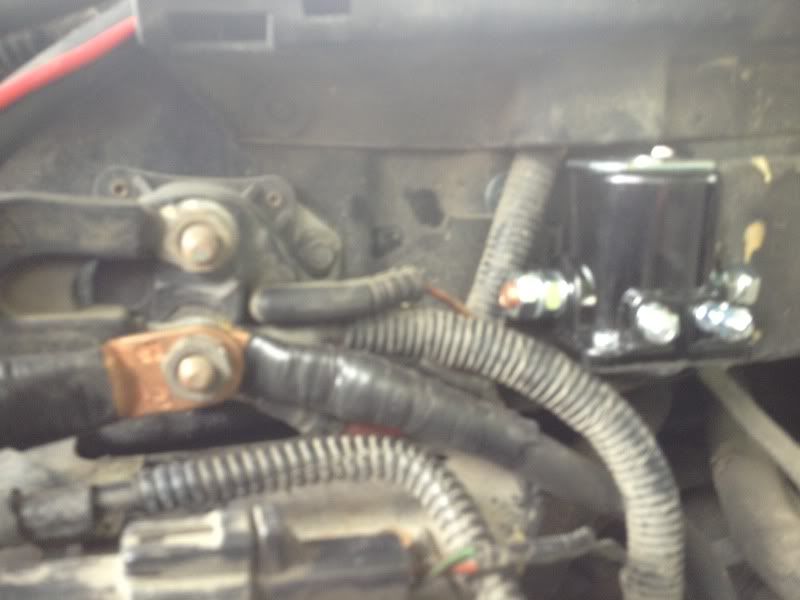

I will install an isolator to charge the two batteries in a later step. Just going over the basics now.
Once I installed the 2nd relay, it was time to run wires from the starter solenoid to the new relay. Again, you need to only replace/add better ga. wire to the ground and 12v supply location. I precut the wires and estimated around 7 ft from the starter location to the relay. So i left the wires around the relay and ran them to the starter for connecting them. Once I get them connected to the starter, I will come back and attach them to the appropriate spots on the relay.
Here is a shot of my ratchet on the ground bolt for the enginge and starter. Please not, this has two bolts. Make sure you only take off the first one and keep the one behind it secure.(you dont want to loosen it up and have to replace a gasket from the transfercase and transmission).
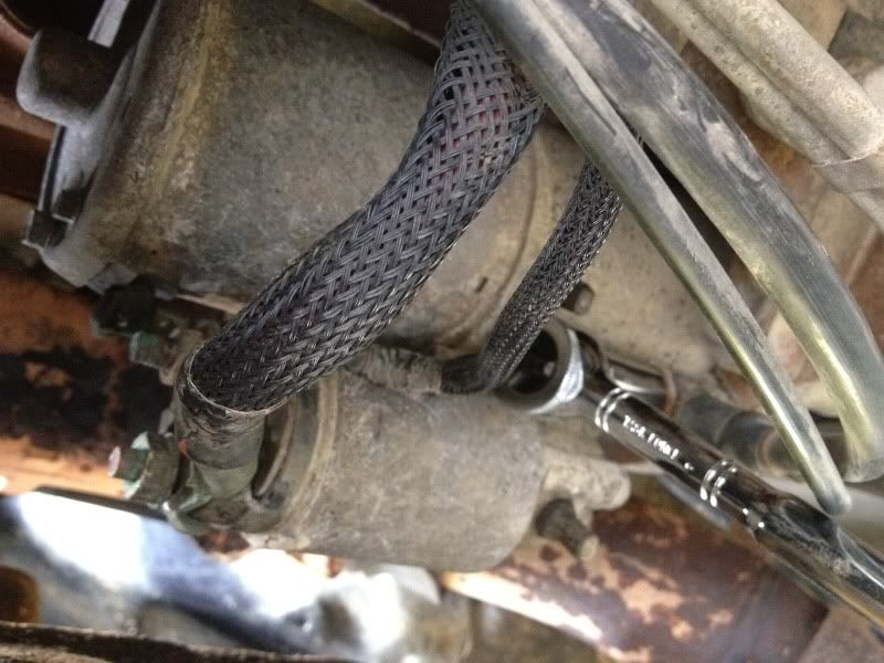
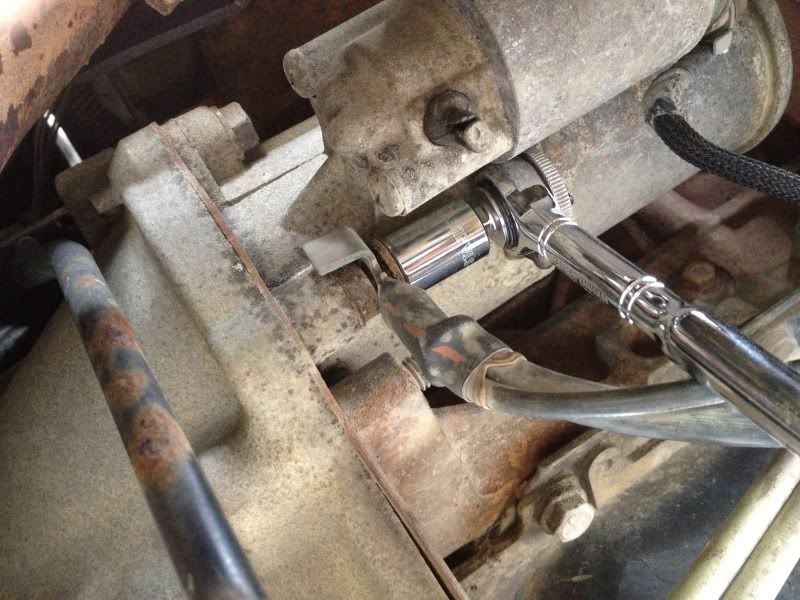
With the top nut off(holding the wire), and the 2nd nut still on, holding the starter to the mount.

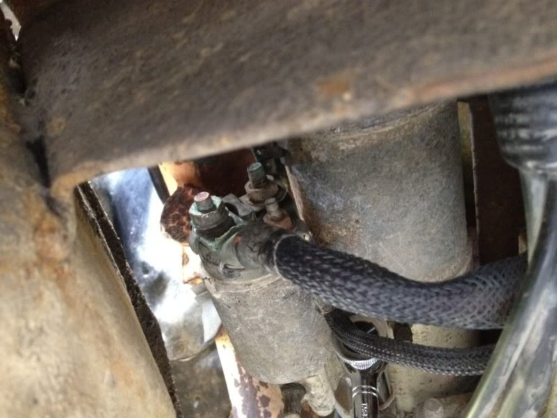
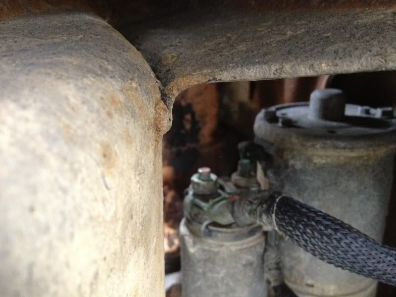
Once the nut is off, replace the factory wire and your new 1ga. wire on top of one another for a good connection, then tighten the bolt back on.
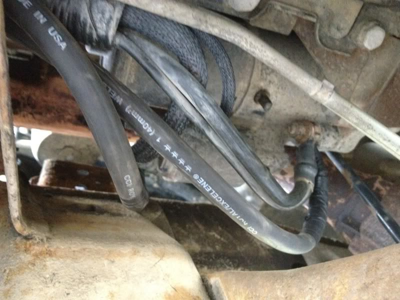
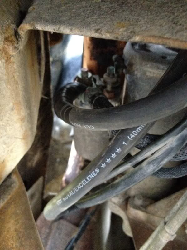
Now we need to do the same thing to the 12v supply.
The large wire, with the covering over it is the 12v supply to the starter.
I know alot of us members have quite a few electrical components running off factory wiring and our factory alternator. Hid's, Amps, Winches, Aftermarket HU's, Off Road Lights, Power inverters, CB's, etc.
Hence, I thought it could be very useful to find a place to install an extra battery for reserve power or to integrate into the factory system. This would require a few modifications;
First, under our hood there is little to now room. So modifications had to be made and something had to be moved to another location. Almost all batteries need to be close to level for optimal efficiency and lifespan. Plus, what better place to protect a battery, than under the hood. (I didn't want the battery taking space up in the cab)
Second, I wanted to make the 2nd battery strictly for Starting and running critical applications(fuel pumps, winches, starter, ignition system).
Third, I was debating on whether or not to have the alt continuously charge the 2nd battery. Then decided to go ahead and use a battery Isolator to charge both the batteries simultaneously, but separate them when the vehicle is off.
Once all that was contemplated about, I needed to find out the usage of all my components and the stress it would put on my alternator. Hence, I've been trying to find some info on the amps of our factory alt. but have yet to find a reliable source, so I would assume its in the range of 100-130 amps.
Mathematically, this would mean; (this is running at full capacity)
note: anything over, and your alt. will be unable to run your components and effective charge your batteries. The alt. needs to be somewhat > than the power you are pulling. Alts. are rated mainly at max ouput and not at idle. So consider this when doing your install and choosing an alt.
Here are the specs I calculated;
Amps = Watts / Volts
For a 100 amp Alt, you could get approx.
1440.000000 watts
For a 130 amp Alt, you could get approx.
1872.000000
And a 180 aftermarket alt.
2592.000000
So I decided to go ahead and do the second battery and change to a 180 alt. I also wanted to upgrade the factory 4ga and 6ga wire to a better, thicker conductor. I went with 1ga mining cable, (it was a little bit of over kill) but being in a mining community I get it fairly cheap. ($1.50 per foot). Holds upwards around 500amps and 600 volts. 30ft of it weighed in about 35lbs. I also decided to upgrade all wiring that charges, starts, and runs the truck.
Now for wiring the starter with better wire.
DISCONNECT YOUR BATTERY FIRST****
You only need to upgrade the 12v supply and the ground. The other smaller red wire, is the ignition lead.
Note: power is always running to the starter, however, the starter solenoid only engages when the ignition is turned on. Due to the harsh winters here, I wanted to have amps running from both the batteries to starter. There are many ways to wire this up, but this is my method and how it benefited my application.
I used an extra starter relay, to only engage the second battery when the ignition is turned over. Thus it isolates the 12v supply from each respective battery when the ignition is not engaged(for starting). Once the truck is cranked, the batteries separate. This makes certain that my truck always has voltage and amps to crank reguarless of how much power is out of the primary battery.
You can see the second starter relay, with the wires unattached and mounted to firewall. Make sure you secure the relay using a grounded location, it requires this to work properly. I used the factory ground location and bolt to attach it.
I will install an isolator to charge the two batteries in a later step. Just going over the basics now.
Once I installed the 2nd relay, it was time to run wires from the starter solenoid to the new relay. Again, you need to only replace/add better ga. wire to the ground and 12v supply location. I precut the wires and estimated around 7 ft from the starter location to the relay. So i left the wires around the relay and ran them to the starter for connecting them. Once I get them connected to the starter, I will come back and attach them to the appropriate spots on the relay.
Here is a shot of my ratchet on the ground bolt for the enginge and starter. Please not, this has two bolts. Make sure you only take off the first one and keep the one behind it secure.(you dont want to loosen it up and have to replace a gasket from the transfercase and transmission).
With the top nut off(holding the wire), and the 2nd nut still on, holding the starter to the mount.
Once the nut is off, replace the factory wire and your new 1ga. wire on top of one another for a good connection, then tighten the bolt back on.
Now we need to do the same thing to the 12v supply.
The large wire, with the covering over it is the 12v supply to the starter.