How to: Keep stereo on until you take your key out and open the door.
 04-12-2013, 06:53 PM
#1

For the older generation of trucks, or ones that the HU cuts off with the key. (Pre 2003)
Mod- This setup will allow your head unit to function as normal, but the head unit will stay on until you turn off the key and open the door.
Note: This is for most 99-03 F150 XLT's. Ones that have positive door triggers. If you have a negative door trigger, contact me and I will send you the schematics or read the last post by me(they are completely different) but use the same materials.
Materials:
1) Standard $4.00, 4 or 5 pin SPST relay. These are normally open, and close to complete a ciruit when current is applied.
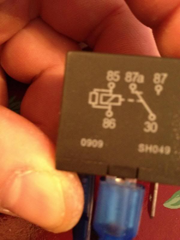
2) A standard SPDT relay. These are normally closed(complete circuit), but open when power is applied. If you ask your auto parts store for an F-150 fuel pump relay, they will give you this exact relay.
3)10ft of 16-18ga wire.
4) Bag of 1/4" female connectors
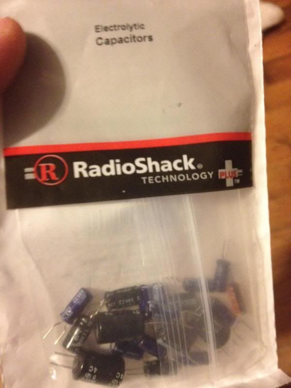
5) 1 (6 or 10) amp diode ($.99 at radio shack)
6) Zip ties
7) Electrical Tap
8) Convenient location to mount the relays.
9) wire cutters/ something to splice with
10) Optional** 47uF capacitor($.29) to keep the stereo from popping and cutting off abruptly.
Pictures of some of the materials and links
1) Standard SPST relay, 4 or 5 pin both work for this application.
http://shop.advanceautoparts.com/web...chTerm=relay+#
2) Standard SPDT relay,
http://shop.advanceautoparts.com/web...zoneAssigned=1

5) 6 amp diode
http://www.radioshack.com/product/in...ductId=2062591

10)* Small uF capacitor (any cheap one will work)
http://www.radioshack.com/product/in...uctId=12460932
Step 1:
** Remove negative battery terminal**
Step 2: Gaining access behind the stereo
Remove your factory or aftermarket radio from the dash. You will need access to the factory wiring (if using a OEM HU), or you will need access to the aftermarket plug(if using aftermarket HU).
For Aftermarket Stereos
1) Find the +12V accesory wire on your aftermarket harness(Usually a Red Wire). This wire will always read +12V when the key is in the following positions: turned back, on ACC, or on Run. It will read 0V when the key is off. Once you have located that wire, you will need to cut it in half (leave room on each end to splice wires). Once you have cut the ACC wire on your aftermarket plug, go to the wire that is no longer connected to the plug. Splice into this wire and run a strand of 16-18ga wire to the location of your relays.
2) Now located the other part of the Red/Acc wire which is still attached to the aftermarket plug. Splice into it with another strand of 16-18 ga. wire and run it to the location of your relays.
Here are some color codes for the aftermarket plug:
The color codes(for metra plugs) are the same for all 97-03 models. Only the plug arrangement is different.
Wire Color----Function
Red------------+12 Volt Accessory
Yellow---------+12 Volt Constant
Black-----------Chassis Ground
Black/White ----Signal Ground (connect with ground wire)
Orange---------Illumination
Orange/Black----Dimmer
White-----------Left Front Speaker +
White/Black-----Left Front Speaker -
Gray------------Right Front Speaker +
Gray/Black------Right Front Speaker -
Green-----------Left Rear Speaker +
Green/Black -----Left Rear Speaker -
Violet -----------Right Rear Speaker +
Violet/Black------Right Rear Speaker -
Other useful info can be found here:
https://www.f150forum.com/f30/97-03-...basics-154340/
For Factory HU's
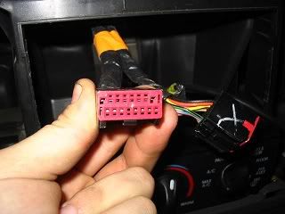
Remover your factory HU. Such that you can locate your factory HU plug. Should look similar to the picture below.
1) Now find the 12V Accesory wire. Usually a Black/Violet wire which will only read +12V when the key is; turned back, on ACC, or on Run.
If you are using a factory HU you will need to cut this wire in half(leave room on both ends to splice), then the first half(the one not connected to the plug any longer) will need to have a spliced wire running down to the location of your relays.
2) After you have ran the wire that is no longer connected to your Plug to your relays, you will need to find the second half of the wire(the part that is still connected to the factory radio plug itself). Splice a wire to the end of this one and run it to the location of your relay.
Step 3:
Locating Door Trigger.
Note: The wire you are looking for is the same one that allows your windows to still operate when the truck is cut off, until you open the door.
The easiest way to do is find the Dark Green/Black wire in your kick panel. I chose to not goes this route because I wanted to keep my kick panel all nice and neat. I did the following:
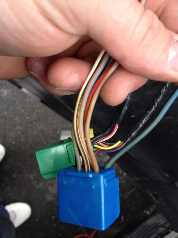
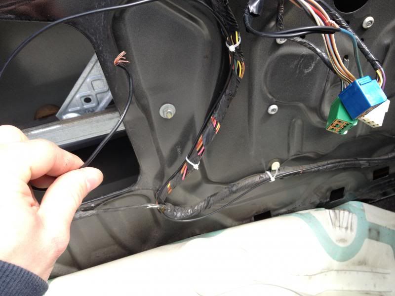
Took the door panel off to give me easy access to the power windows/locks. I located the "Blue" plug for the power windows. The wire you are looking for is the same one that allows your windows to still operate when the truck is cut off, until you open the door. So get in your truck close the door and use a light tester. It will read +12V anytime the trucks accessories are on, and will also read +12V UNTIL YOU OPEN THE DOOR, then it will cut power.
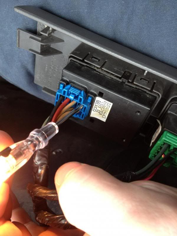
Once I found the wire (Green/Black), the corner pin on the "blue" plug as seen below, I spliced a strand of 16-18ga wire and ran it through the door, into the cab, and to my relays location.
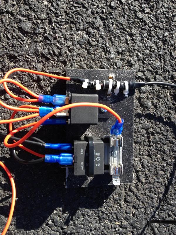
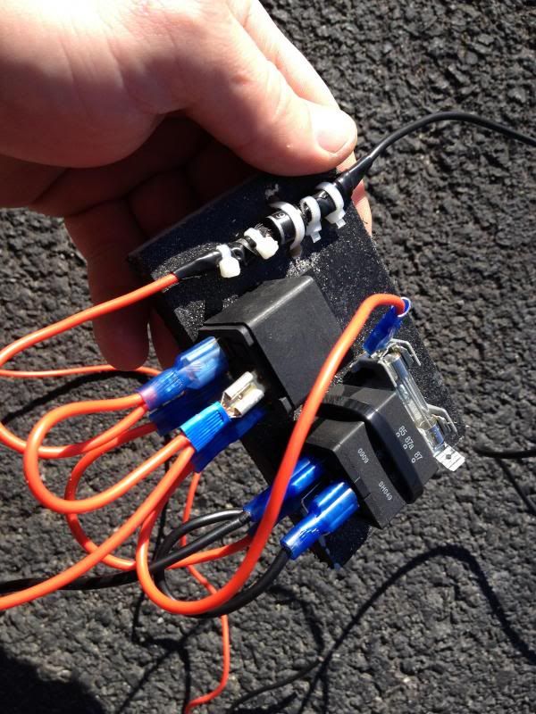
Step 4:
Wiring relays
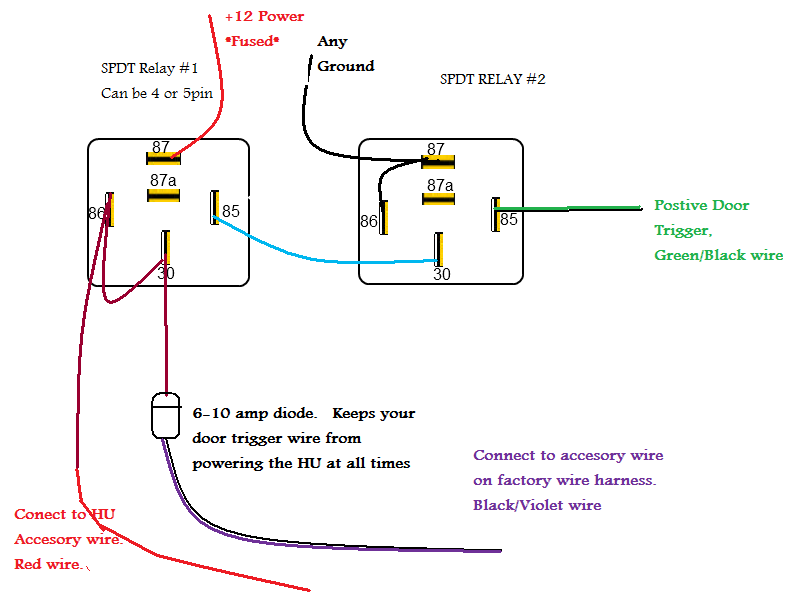
Here is a schematic for reference.
*Use 16-18ga wire and 1/4" female adpaters for all the following connections*
On relay #2:
1) Wire pin#86 to pin#87(don't crimp pin#87 yet) you will be adding another wire to this connector in the next step.
2) Run a strand of wire from pin#87 (should have two wires in pin#87) to any ground location.
3) Attach the Door Trigger wire you ran earlier (from the Green/Black wire) to pin#85
From relay #2 to realy #1
Wire pin#30 on relay #2, to pin#85 on relay #1
Relay #1
1) Wire pin #30 to pin#86 (don't crimp either of these yet)
2) Note* This connection is from the Accessory wire that is still connected to the plug. Connect the HU Accessory wire to pin#86 (Red if you have aftermarket. Black/Violet if you have OEM)
3) Since we have yet to crimp pin#30, we will need to run a short strand of wire to the cathode end (one with the stripe) of the 6amp diode. Now wire the anode (end with no strip) to the HU accessory wire.
Note: This connection is from the Accessory wire that is no longer connected to the plug.
4) Wire pin#87 to a constant 12V supply. *Make sure you fuse this lead*. You can splice into the constant 12V supply on the stereo wiring harness if you like, or run your own.
5) make sure all connections are taped/soldered/ firmly attached, such that they wont ground out.
** You may also add a small cap, in the proper location such that the stereo doesn't cut off abruptly and pop.
Keep reading...
Mod- This setup will allow your head unit to function as normal, but the head unit will stay on until you turn off the key and open the door.
Note: This is for most 99-03 F150 XLT's. Ones that have positive door triggers. If you have a negative door trigger, contact me and I will send you the schematics or read the last post by me(they are completely different) but use the same materials.
Materials:
1) Standard $4.00, 4 or 5 pin SPST relay. These are normally open, and close to complete a ciruit when current is applied.
2) A standard SPDT relay. These are normally closed(complete circuit), but open when power is applied. If you ask your auto parts store for an F-150 fuel pump relay, they will give you this exact relay.
3)10ft of 16-18ga wire.
4) Bag of 1/4" female connectors
5) 1 (6 or 10) amp diode ($.99 at radio shack)
6) Zip ties
7) Electrical Tap
8) Convenient location to mount the relays.
9) wire cutters/ something to splice with
10) Optional** 47uF capacitor($.29) to keep the stereo from popping and cutting off abruptly.
Pictures of some of the materials and links
1) Standard SPST relay, 4 or 5 pin both work for this application.
http://shop.advanceautoparts.com/web...chTerm=relay+#
2) Standard SPDT relay,
http://shop.advanceautoparts.com/web...zoneAssigned=1
5) 6 amp diode
http://www.radioshack.com/product/in...ductId=2062591
10)* Small uF capacitor (any cheap one will work)
http://www.radioshack.com/product/in...uctId=12460932
Step 1:
** Remove negative battery terminal**
Step 2: Gaining access behind the stereo
Remove your factory or aftermarket radio from the dash. You will need access to the factory wiring (if using a OEM HU), or you will need access to the aftermarket plug(if using aftermarket HU).
For Aftermarket Stereos
1) Find the +12V accesory wire on your aftermarket harness(Usually a Red Wire). This wire will always read +12V when the key is in the following positions: turned back, on ACC, or on Run. It will read 0V when the key is off. Once you have located that wire, you will need to cut it in half (leave room on each end to splice wires). Once you have cut the ACC wire on your aftermarket plug, go to the wire that is no longer connected to the plug. Splice into this wire and run a strand of 16-18ga wire to the location of your relays.
2) Now located the other part of the Red/Acc wire which is still attached to the aftermarket plug. Splice into it with another strand of 16-18 ga. wire and run it to the location of your relays.
Here are some color codes for the aftermarket plug:
The color codes(for metra plugs) are the same for all 97-03 models. Only the plug arrangement is different.
Wire Color----Function
Red------------+12 Volt Accessory
Yellow---------+12 Volt Constant
Black-----------Chassis Ground
Black/White ----Signal Ground (connect with ground wire)
Orange---------Illumination
Orange/Black----Dimmer
White-----------Left Front Speaker +
White/Black-----Left Front Speaker -
Gray------------Right Front Speaker +
Gray/Black------Right Front Speaker -
Green-----------Left Rear Speaker +
Green/Black -----Left Rear Speaker -
Violet -----------Right Rear Speaker +
Violet/Black------Right Rear Speaker -
Other useful info can be found here:
https://www.f150forum.com/f30/97-03-...basics-154340/
For Factory HU's
Remover your factory HU. Such that you can locate your factory HU plug. Should look similar to the picture below.
1) Now find the 12V Accesory wire. Usually a Black/Violet wire which will only read +12V when the key is; turned back, on ACC, or on Run.
If you are using a factory HU you will need to cut this wire in half(leave room on both ends to splice), then the first half(the one not connected to the plug any longer) will need to have a spliced wire running down to the location of your relays.
2) After you have ran the wire that is no longer connected to your Plug to your relays, you will need to find the second half of the wire(the part that is still connected to the factory radio plug itself). Splice a wire to the end of this one and run it to the location of your relay.
Step 3:
Locating Door Trigger.
Note: The wire you are looking for is the same one that allows your windows to still operate when the truck is cut off, until you open the door.
The easiest way to do is find the Dark Green/Black wire in your kick panel. I chose to not goes this route because I wanted to keep my kick panel all nice and neat. I did the following:
Took the door panel off to give me easy access to the power windows/locks. I located the "Blue" plug for the power windows. The wire you are looking for is the same one that allows your windows to still operate when the truck is cut off, until you open the door. So get in your truck close the door and use a light tester. It will read +12V anytime the trucks accessories are on, and will also read +12V UNTIL YOU OPEN THE DOOR, then it will cut power.
Once I found the wire (Green/Black), the corner pin on the "blue" plug as seen below, I spliced a strand of 16-18ga wire and ran it through the door, into the cab, and to my relays location.
Step 4:
Wiring relays
Here is a schematic for reference.
*Use 16-18ga wire and 1/4" female adpaters for all the following connections*
On relay #2:
1) Wire pin#86 to pin#87(don't crimp pin#87 yet) you will be adding another wire to this connector in the next step.
2) Run a strand of wire from pin#87 (should have two wires in pin#87) to any ground location.
3) Attach the Door Trigger wire you ran earlier (from the Green/Black wire) to pin#85
From relay #2 to realy #1
Wire pin#30 on relay #2, to pin#85 on relay #1
Relay #1
1) Wire pin #30 to pin#86 (don't crimp either of these yet)
2) Note* This connection is from the Accessory wire that is still connected to the plug. Connect the HU Accessory wire to pin#86 (Red if you have aftermarket. Black/Violet if you have OEM)
3) Since we have yet to crimp pin#30, we will need to run a short strand of wire to the cathode end (one with the stripe) of the 6amp diode. Now wire the anode (end with no strip) to the HU accessory wire.
Note: This connection is from the Accessory wire that is no longer connected to the plug.
4) Wire pin#87 to a constant 12V supply. *Make sure you fuse this lead*. You can splice into the constant 12V supply on the stereo wiring harness if you like, or run your own.
5) make sure all connections are taped/soldered/ firmly attached, such that they wont ground out.
** You may also add a small cap, in the proper location such that the stereo doesn't cut off abruptly and pop.
Keep reading...

The following users liked this post:
dopewaffle (09-11-2014)
 05-06-2013, 05:35 AM
#3
Thanks for sharing  , Moved to How to
, Moved to How to

