Installing electronic Boost Gauge with how to pics
 02-14-2013, 12:03 PM
#1
I have been wanting to do this project for some time now and finally got a chance and down time to do it. I ordered my electronic boost gauge from eBay and the total was $27.00 shipped. I was looking for a blue digital gauge to match the dash gauges and maintain somewhat of a factory look. I don't have a 4x4 so I choose to remove the pointless coin holder where the 4x4 selection **** goes and install the gauge there, its not so in your face as opposed to the Rosh vent location which also limits the function of the air vent.
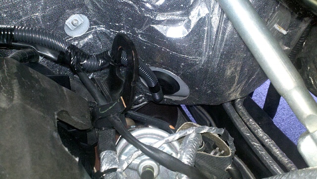
I located a rubber grommet just behind the gas and break pedal
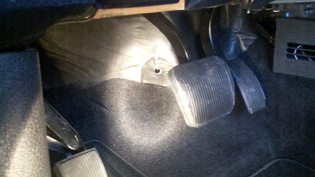
Pull the precut insulation back and expose the rubber grommet
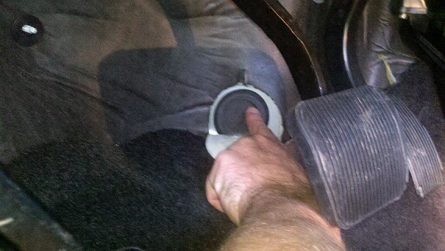
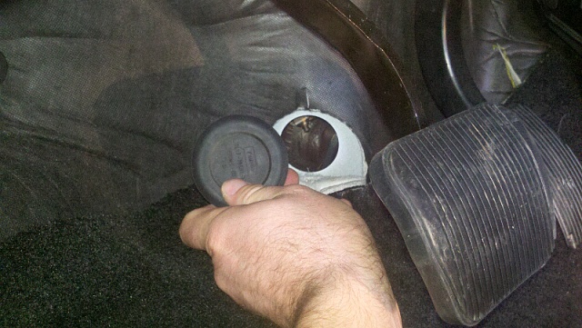
The grommet is very easy to just pull out. Just pull the rubber grommet and it comes right out.
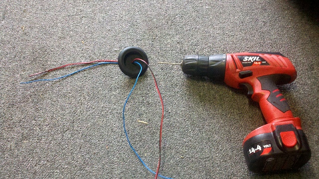
I drilled a small hole through the grommet smaller than the three wires that have to be pushed through so as to keep it water tight
Here is a pic with the wires and grommet installed back in the firewall. It is located down below and behind the drivers side turbo.
You will need to remove the cowling from the top of your engine. Then you will see a sensor that has (2) two bolt holes in it but uses only one bolt to hold it in place. I used this location to mount the pressure sensor for the boost gauge. Just remove the bolt and place the boost gauge sensor ontop and re-bolt them together back to the top of the engine.
I located a rubber grommet just behind the gas and break pedal

Pull the precut insulation back and expose the rubber grommet

The grommet is very easy to just pull out. Just pull the rubber grommet and it comes right out.

I drilled a small hole through the grommet smaller than the three wires that have to be pushed through so as to keep it water tight

Here is a pic with the wires and grommet installed back in the firewall. It is located down below and behind the drivers side turbo.
You will need to remove the cowling from the top of your engine. Then you will see a sensor that has (2) two bolt holes in it but uses only one bolt to hold it in place. I used this location to mount the pressure sensor for the boost gauge. Just remove the bolt and place the boost gauge sensor ontop and re-bolt them together back to the top of the engine.
Last edited by BoostedFx; 02-14-2013 at 12:57 PM.
 02-14-2013, 12:22 PM
#2
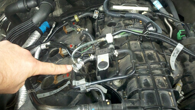
Next I covered the wires in black plastic corrugated wire protection. This makes look more factory and also protects the wires from direct heat. Im.holding a screw driver to point to the covered wires
I covered the wires all the way to the rubber grommet and used black electrical tape about every 6" to keep it closed. You can find plenty of places to attach the corrugated wire to keep it away from turbo exhaust down low.
I tapped into fuse #38 on the passenger side fuse panel. I already have had a distribution switch installed under my dash below the steering wheel. I used it because I can turn off the gauge if I want, I also run my blue foot well lighting off of this. It has 6 spaces for separate accessories each with its own on/off switch.

I covered the wires all the way to the rubber grommet and used black electrical tape about every 6" to keep it closed. You can find plenty of places to attach the corrugated wire to keep it away from turbo exhaust down low.

I tapped into fuse #38 on the passenger side fuse panel. I already have had a distribution switch installed under my dash below the steering wheel. I used it because I can turn off the gauge if I want, I also run my blue foot well lighting off of this. It has 6 spaces for separate accessories each with its own on/off switch.
Last edited by BoostedFx; 02-14-2013 at 01:03 PM.
02-14-2013, 12:37 PM
#3
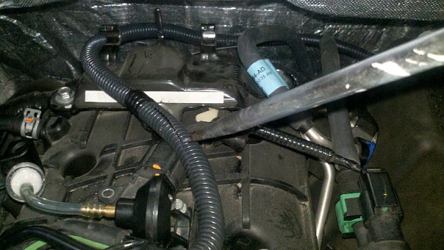
I tapped into a air line that runs from the passenger side turbo outlet tube. This Air tube runs from the turbo to the after cooler, it has a small air line coming off it that runs up to the top of the engine. I cut the air line where it transitions into a rubber tube and installed the plastic T that is provided with the Boost Gauge kit. Connect the provided air hose from the T to the pressure sensor and be sure to put the in-line air filter in to keep and dust out.
Here is another view of the tape in.
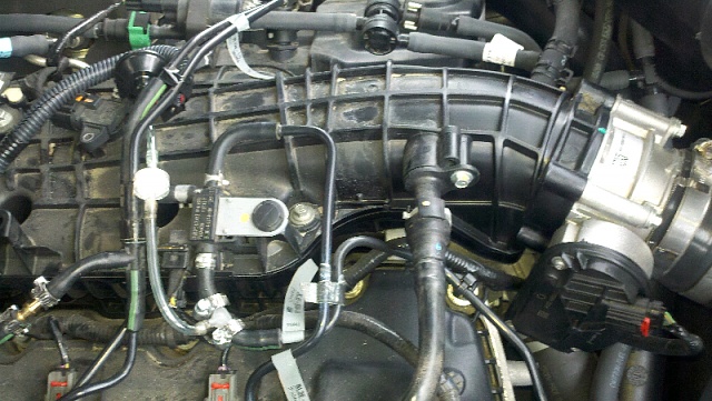
NOTE: I did cut into a line that was recommend on another thread but I only read (-) numbers. That line was a vacuum line and DID NOT provide both vacuum and boost as stated on another thread. I had to repair that cut and find a different location. The line I used provides (+) positive readings ONLY andis a is extremely good source for accurate (+) positive readings. I'm only concerned with boost anyways as that is where you get the most power from.
The following users liked this post:
TXAG07 (02-14-2013)
02-14-2013, 12:45 PM
#4
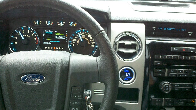
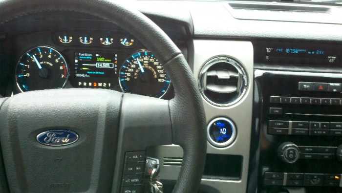
Here is the finished look. The boost gauge is works perfectly and gives very accurate readings it also matches perfect with the interior.
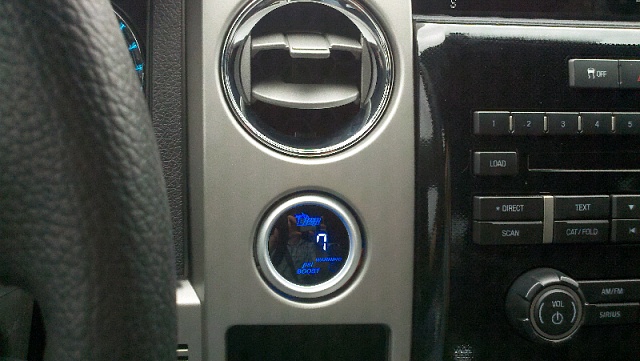
I find the problem is I tend to watch it alot, but I'm sure I won't be so fixated on it as I get used to it.

I find the problem is I tend to watch it alot, but I'm sure I won't be so fixated on it as I get used to it.
 02-14-2013, 01:06 PM
#6

Boosted, that is a clean looking job, the gauge blends in great. I am new to the turbo ecoboost stuff, can you educate us to why you installed this gauge, what are you looking to get out of the gauge and does this gauge read both turbo's and the boost/pressure output being released?
02-14-2013, 05:15 PM
#7
Boosted, that is a clean looking job, the gauge blends in great. I am new to the turbo ecoboost stuff, can you educate us to why you installed this gauge, what are you looking to get out of the gauge and does this gauge read both turbo's and the boost/pressure output being released?
Last edited by BoostedFx; 02-14-2013 at 05:37 PM.
Trending Topics
02-14-2013, 05:43 PM
#8

I tapped into a air line that runs from the passenger side turbo outlet tube. This Air tube runs from the turbo to the after cooler, it has a small air line coming off it that runs up to the top of the engine. I cut the air line where it transitions into a rubber tube and installed the plastic T that is provided with the Boost Gauge kit. Connect the provided air hose from the T to the pressure sensor and be sure to put the in-line air filter in to keep and dust out.
Attachment 193055
Here is another view of the tape in.
Attachment 193057
NOTE: I did cut into a line that was recommend on another thread but I only read (-) numbers. That line was a vacuum line and DID NOT provide both vacuum and boost as stated on another thread. I had to repair that cut and find a different location. The line I used provides (+) positive readings ONLY andis a is extremely good source for accurate (+) positive readings. I'm only concerned with boost anyways as that is where you get the most power from.
It looks like you cut into the line after the check valve. Had you moved it to the other side of the check valve, you would get vacuum and boost signals on your gauge. Here is a link to where I put my "t" in and I get both.
https://www.f150forum.com/f38/ecoboo...l-pics-108180/
I started out using the coin holder but ended up moving into the vent for better visibility. Cost me nothing to put it in the vent.
https://www.f150forum.com/f38/instal...sh-pod-189018/
Hope that new vacuum location helps you.
Jeff
02-14-2013, 07:12 PM
#9
It looks like you cut into the line after the check valve. Had you moved it to the other side of the check valve, you would get vacuum and boost signals on your gauge. Here is a link to where I put my "t" in and I get both.
https://www.f150forum.com/f38/ecoboo...l-pics-108180/
I started out using the coin holder but ended up moving into the vent for better visibility. Cost me nothing to put it in the vent.
https://www.f150forum.com/f38/instal...sh-pod-189018/
Hope that new vacuum location helps you.
Jeff
Thanks again.
Don