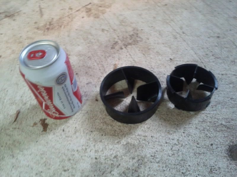
Ecoboost, twirly things in the intake pipes
 12-14-2011, 01:35 PM
#131
Converted

Holy Cow! There is an upgrade to these things!
http://www.ebay.com/itm/Ford-Turbona...item3a6a71d0eb
Feel free to flame away! I thought this was hilarious!
http://www.ebay.com/itm/Ford-Turbona...item3a6a71d0eb
Feel free to flame away! I thought this was hilarious!
I am thinking of doubling them up for more increase......

 12-14-2011, 02:27 PM
#132
FX4 SCrew TT'd V6
Thread Starter
Holy Cow! There is an upgrade to these things!
http://www.ebay.com/itm/Ford-Turbona...item3a6a71d0eb
Feel free to flame away! I thought this was hilarious!
http://www.ebay.com/itm/Ford-Turbona...item3a6a71d0eb
Feel free to flame away! I thought this was hilarious!
12-14-2011, 11:09 PM
#133
Member

Join Date: Nov 2011
Posts: 40
Likes: 0
Received 0 Likes
on
0 Posts
I really wonder what these things do though. I saw on the page that 30 of them had been sold, so they gotta work right?

 12-15-2011, 05:00 AM
#136
Bug Slinger
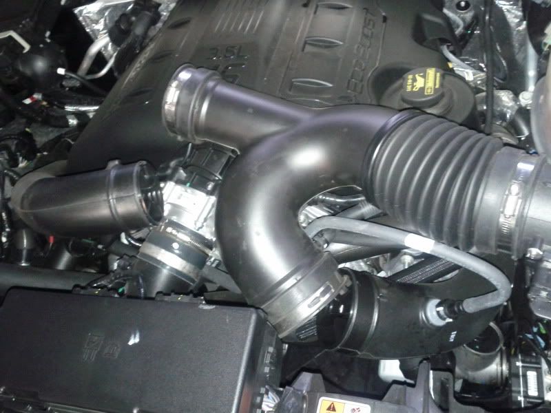
From a Aircraft Mechanics perspective... in relation to these parts...1. look at what is up stream from where these are located in the system.. they are directly after the Y pipe and flexible section of pluming.. logic would dictate that they put them in the system in an attempt to straighten out some of the airflow before entering the turbos... 2.. For the difference in the size of the pluming going to each turbo... Air like water likes to take the path of least resistance.. The right turbo has more of a straight shot threw the y pipe then the left turbo.. and the ratio in size is an effort to keep the volume of air going to both turbos the same after the Y.. just an A&P's thought on the subject..
The following users liked this post:
Aj06bolt12r (04-06-2016)
12-15-2011, 07:16 AM
#137

We've moved on past the subject of why air flows through a tube with lower air pressure than outside it, toward the turbo much like water drains down a drain. We are now designing a twin turbo system with an air induction design to the turbo's that's perty much a straight shot to the turbos and a programing/driver for the puter to operate with 2 mass sensors. Note you don't see square tubes in air induction systems unless they have a round insert inside of them. The twirly things are an engineering fix for the fu__ed up design. It's pure Genious ! LOL On a short note my 3.7 burned 1.3 gallons of gas an hour this last time, with 12.5 gallons of shell 87 after 9.5 hours of cross town expressway and stop and go driving with no warm up time and little idle time except at the stop lights. What are your EB's using an hour ? I'll start a thread if I get time. I had a 4 cyl car that got 36mpg. since new, and after 4 years was averaging driving 44 mph and using just over 2 gallons of gas an hour.
Last edited by papa tiger; 12-15-2011 at 08:57 AM.
12-15-2011, 07:23 AM
#138
ETTYOCEO �

Originally Posted by RedOctober5
I have read thru the hole thread... and I haven't really seen any one talk about it..
From a Aircraft Mechanics perspective... in relation to these parts...1. look at what is up stream from where these are located in the system.. they are directly after the Y pipe and flexible section of pluming.. logic would dictate that they put them in the system in an attempt to straighten out some of the airflow before entering the turbos... 2.. For the difference in the size of the pluming going to each turbo... Air like water likes to take the path of least resistance.. The right turbo has more of a straight shot threw the y pipe then the left turbo.. and the ratio in size is an effort to keep the volume of air going to both turbos the same after the Y.. just an A&P's thought on the subject..
12-15-2011, 07:56 AM
#139
Junior Member

Join Date: Dec 2011
Location: Western Canada
Posts: 5
Likes: 0
Received 0 Likes
on
0 Posts
No, impossible to be flow restrictors. They're guide vanes, in order to induce a swirl (spin the flow how we want it) or they eliminate any incoming swirl (again, to orientate the flow how we want it)
12-15-2011, 09:01 AM
#140
 I can only imagine the bad thoughts going thru the pilots mind of the Harrior when he hears that popping sound thru the turbojet.
 :wheelchair :