When you click on links to various merchants on this site and make a purchase, this can result in this site earning a commission. Affiliate programs and affiliations include, but are not limited to, the eBay Partner Network.
Someone have a vacuum diagram, pics, description or anything from AC when i buy my truck all the lines are off .
i fix the 4wd lines but the others i dont have any idea how to connect.
from the vacuum reservator one line end in check valve and then the line is cut off..
from inside of cabin have a black line is out and plug in a T lines and then another vacuum reservator.
thanks for your reply, unfortunately the sticker have gone
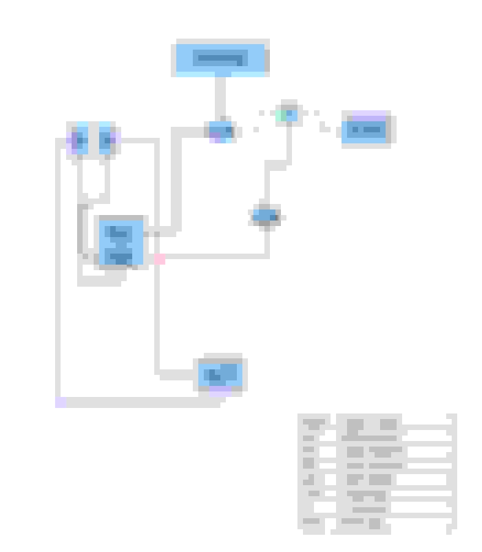
1.- The cut line
2.- black line, they go to the cabine.
3.- This line go to engine
4.- Vent front differential
5.- black line to the lower vacuum reserve
6.- red line, is the other side from the number 1; they go a vacuum reserve (upper)
Huh, someone molested your lines lol. Yellow is suppose to be under the dash. Well, in order to know what's going on or what's not, I need a pick of your throttle body where the vac lines enter it. For the 03, that SHOULD be on the pass side of the T-body.
Also need a pic of the EVR/EGR van lines and of the firewall purge solenoid above or over by the brake booster. It's where that white line should travel.
Great Idea! Yea, the emissions harness is incomplete. Also keep in that the 02's systems was one of a kind. Ford changed the 02's. Not so much routing, but actual parts of the emission sytem. Ford reverted back to the 01 style with the 03 model years. So if you seen anything screwy on that 02, that's why lol.
White should route from the trunk line over by the battery/firewall, run to the EVR and end by the booster, (by the white and green rubber hose connects on the FW) Red from the throttle body plenum or elbow (vac supply) to the fuel regulator (FR) Geen from the EVR out to the EGR in.
The black trunk line is the supply for the harness and also runs into the cab.
Pink and Blue are correct 2wd/4wd actuator.
So again what's up with yellow ? And what's up with the white line being hacked ? Did someone try to eliminate the EGR system?
I don't really know he wants to do the previous owner..
I supouse that the "T check valve" that feed inside the cabine and upper reservoir from EGR has broke and then him put the "yellow T" only for connect the hose to something...
I replace the 'Yellow T' (thath really is a plug) for a check valve in T.
The broken hose is the red line in the diagram, i put with a 'T' connector to the line of EGR, this feed the vacuum reservoir of solenoids..
The only bad thing is that now all lines are black.. but really i don't think that matters xD
Well as long as they are all going to correct locations. Also sealing those lines/boots, T's can be a chore. It depends upon what was used. From what I can see, the yellow line looks nice and tight! But, if there's anything questionable at the seals, use MEK to seal the joints. Here's how, -
Also, what you have to be careful of is not to pinch off the 90's. Pushing the hose in to far is easy to do.
Lets see what else, - well confirm idle (warm idle) is between 700-750 rpm and steady. You should in fact be at 729/730 to be vacuum perfect. Can't really stray too far from perfect to mark a vacuum problem with these trucks...engines.
 04-16-2015, 02:38 PM

 .
.