
Remote Controlled Lighting / Off road Flood lights

Thread Starter
Senior Member
Joined: Nov 2014
Posts: 152
Likes: 4
From: Stillwater, OK
7/23/2017 UPDATE: Trying to update my photos after the great Photobucket Disaster. Proving more difficult than I first thought to rehost all the photos, and relink. Latest photos are updated, and I am considering just starting a new thread in the Builds Section with my latest setup. But here's a current picture so save you a click.

**I know, I know, another lighting post!**
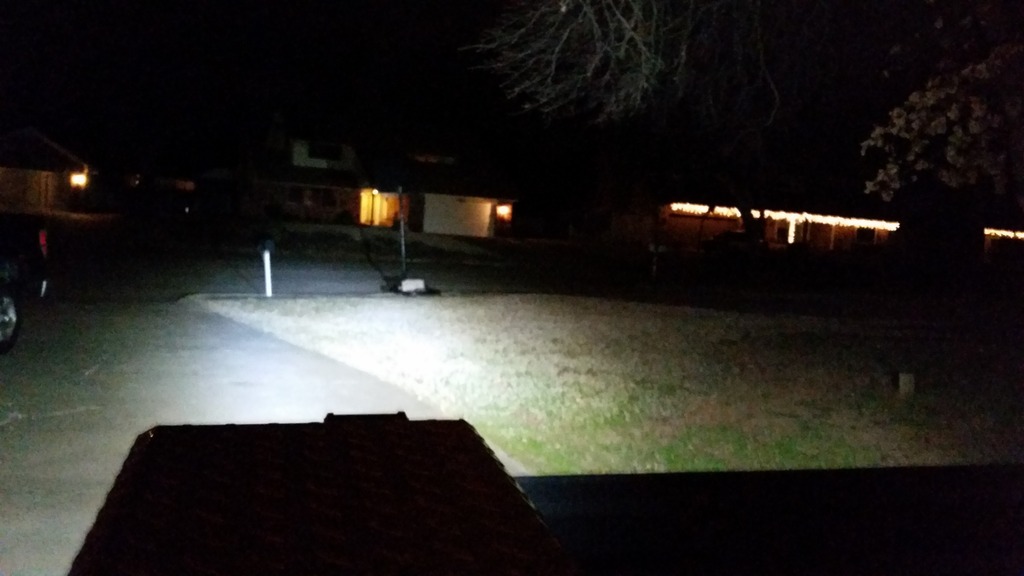
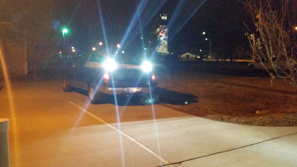
I was poking around looking for a place to put this in case anyone wanted to see. I'm still waiting for better weather to get out and take better pictures of the light output, but this will do for now!
2 LED Cubes found for CHEAP on amazon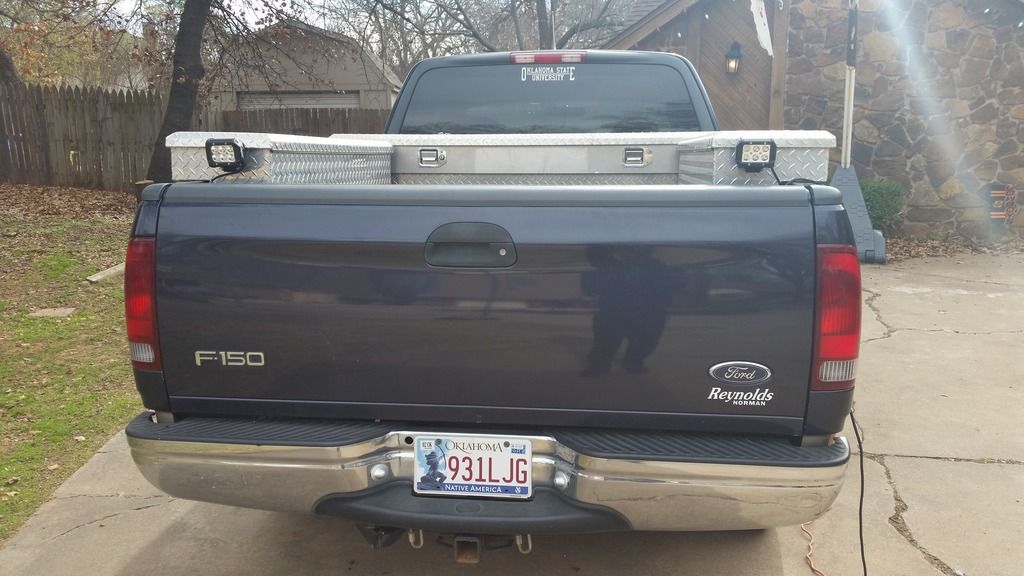
I have the lights going through an 8 channel relay board wired up to an Arduino Uno microcontroller getting signals from a 4 button key fob and 4 channel momentary receiver.

For now, I have the lights on 2 seperate channels/buttons, but will eventually combine when I get more lights to use.
There are 8 relays, and 4 buttons on the key fob, so I just pre-wired 4 toggled channels. I am using 2 for the back lights, and will use 1 for the front flood lights when I get them installed, one for bed + toolbox lights, and maybe an air compressor in the future.
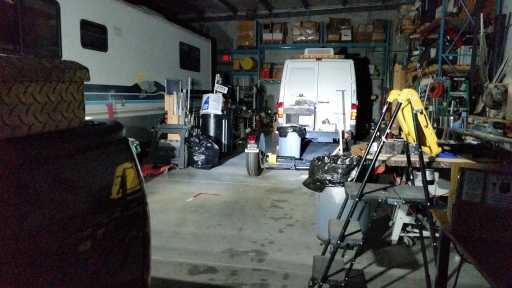
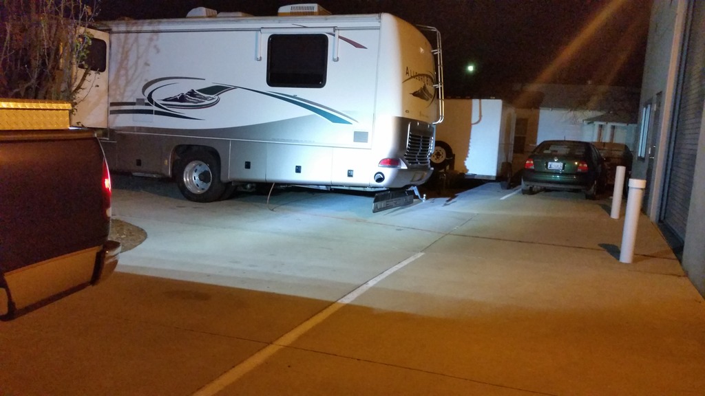
Enough words, here some pictures from the night I installed them!

And all of this is completely isolated from my electrical system. I am running a dry-cell battery that we use in our robotics (works awesome!) going to a terminal block, grounding block, fuse block, 2 12v outlets, and to the black box that houses the micro-controller and relays.
Immediate future plans are to install the front flood/ fog lights, and install the bed lights. I also will be programming in a timer for the bed lights.
Somewhere in the future is a headache rack mounted solar panel, OBA (which i have), and start making more remote controlled light modules!
This was a fun project, and is ever evolving! I would love some feedback, and see some more pictures of the off road lighting installations!
**I know, I know, another lighting post!**
I was poking around looking for a place to put this in case anyone wanted to see. I'm still waiting for better weather to get out and take better pictures of the light output, but this will do for now!
2 LED Cubes found for CHEAP on amazon

I have the lights going through an 8 channel relay board wired up to an Arduino Uno microcontroller getting signals from a 4 button key fob and 4 channel momentary receiver.

For now, I have the lights on 2 seperate channels/buttons, but will eventually combine when I get more lights to use.
There are 8 relays, and 4 buttons on the key fob, so I just pre-wired 4 toggled channels. I am using 2 for the back lights, and will use 1 for the front flood lights when I get them installed, one for bed + toolbox lights, and maybe an air compressor in the future.
Enough words, here some pictures from the night I installed them!


And all of this is completely isolated from my electrical system. I am running a dry-cell battery that we use in our robotics (works awesome!) going to a terminal block, grounding block, fuse block, 2 12v outlets, and to the black box that houses the micro-controller and relays.

Immediate future plans are to install the front flood/ fog lights, and install the bed lights. I also will be programming in a timer for the bed lights.
Somewhere in the future is a headache rack mounted solar panel, OBA (which i have), and start making more remote controlled light modules!
This was a fun project, and is ever evolving! I would love some feedback, and see some more pictures of the off road lighting installations!
Last edited by TJ1996; Jul 23, 2017 at 12:12 PM. Reason: Updated Photo

Senior Member
Joined: Dec 2015
Posts: 175
Likes: 17
From: Ohio
**I know, I know, another lighting post!**
I was poking around looking for a place to put this in case anyone wanted to see. I'm still waiting for better weather to get out and take better pictures of the light output, but this will do for now!
2 LED Cubes found for CHEAP on amazon here.
I have the lights going through an 8 channel relay board wired up to an Arduino Uno microcontroller getting signals from a 4 button key fob and 4 channel momentary receiver.
For now, I have the lights on 2 seperate channels/buttons, but will eventually combine when I get more lights to use.
There are 8 relays, and 4 buttons on the key fob, so I just pre-wired 4 toggled channels. I am using 2 for the back lights, and will use 1 for the front flood lights when I get them installed, one for bed + toolbox lights, and maybe an air compressor in the future.
Enough words, here some pictures from the night I installed them!


And all of this is completely isolated from my electrical system. I am running a dry-cell battery that we use in our robotics (works awesome!) going to a terminal block, grounding block, fuse block, 2 12v outlets, and to the black box that houses the micro-controller and relays.

Immediate future plans are to install the front flood/ fog lights, and install the bed lights. I also will be programming in a timer for the bed lights.
Somewhere in the future is a headache rack mounted solar panel, OBA (which i have), and start making more remote controlled light modules!
This was a fun project, and is ever evolving! I would love some feedback, and see some more pictures of the off road lighting installations!
I was poking around looking for a place to put this in case anyone wanted to see. I'm still waiting for better weather to get out and take better pictures of the light output, but this will do for now!
2 LED Cubes found for CHEAP on amazon here.
I have the lights going through an 8 channel relay board wired up to an Arduino Uno microcontroller getting signals from a 4 button key fob and 4 channel momentary receiver.
For now, I have the lights on 2 seperate channels/buttons, but will eventually combine when I get more lights to use.
There are 8 relays, and 4 buttons on the key fob, so I just pre-wired 4 toggled channels. I am using 2 for the back lights, and will use 1 for the front flood lights when I get them installed, one for bed + toolbox lights, and maybe an air compressor in the future.
Enough words, here some pictures from the night I installed them!
And all of this is completely isolated from my electrical system. I am running a dry-cell battery that we use in our robotics (works awesome!) going to a terminal block, grounding block, fuse block, 2 12v outlets, and to the black box that houses the micro-controller and relays.
Immediate future plans are to install the front flood/ fog lights, and install the bed lights. I also will be programming in a timer for the bed lights.
Somewhere in the future is a headache rack mounted solar panel, OBA (which i have), and start making more remote controlled light modules!
This was a fun project, and is ever evolving! I would love some feedback, and see some more pictures of the off road lighting installations!
The reason I want to use a Rasp Pi is for a touch screen controller and a BT controller that is connected to an app on my phone. Nice to see another person tinker with micro controllers.
Have you had any issues with the arduino running outside without any vibration resistance or anything?
Thread Starter
Senior Member
Joined: Nov 2014
Posts: 152
Likes: 4
From: Stillwater, OK
Hey man, great looking project! I was actually wanting to do something similar, using a Raspberry Pi 2, or a Raspberry Pi 2 connected to an UNO. Can you give me the wiring details for the lights off the relays? I'm not sure if I'm going to need extra power to power everything.
The reason I want to use a Rasp Pi is for a touch screen controller and a BT controller that is connected to an app on my phone. Nice to see another person tinker with micro controllers.
Have you had any issues with the arduino running outside without any vibration resistance or anything?
The reason I want to use a Rasp Pi is for a touch screen controller and a BT controller that is connected to an app on my phone. Nice to see another person tinker with micro controllers.
Have you had any issues with the arduino running outside without any vibration resistance or anything?
Well thank you! Making a touch screen to control lights has been on my dream to-do list for a while now. Over the summers, I do custom electrical wiring and lighting installations on semi trailers for high school bands.
My brother got a RPi2 for Christmas, and we're planning on making a dash cam out of it that has a wifi dongle, so it will upload all the video to our server when it finds an open wifi network.

Anyway, as far as just bluetooth connectivity, I had found a bluetooth relay board a while back on ebay.
It comes with its own app from the Play store, but I think you could pretty easily make your own that follows the proper protocols.
As far as my wiring, I tried to make it plug and play.
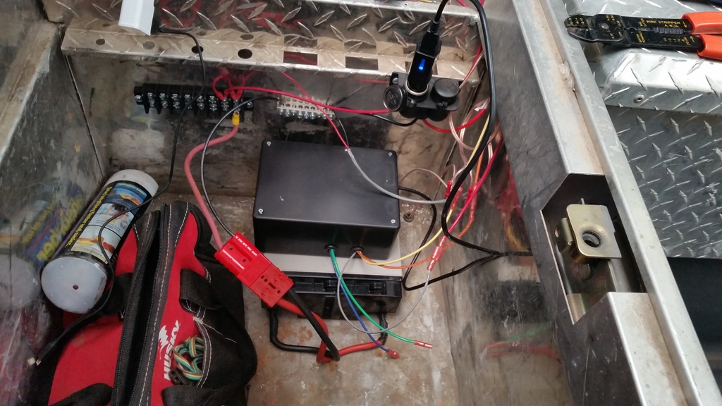
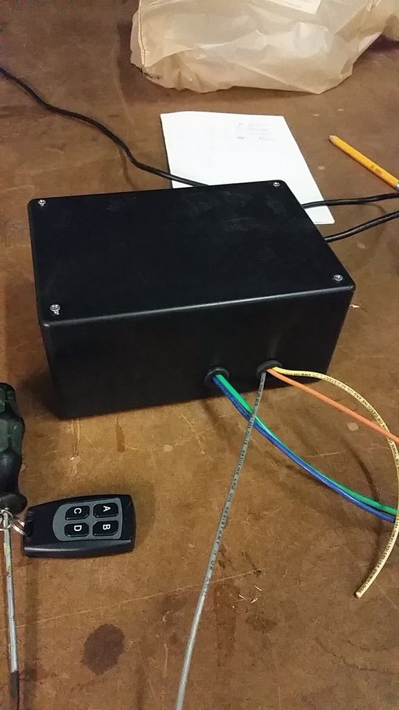
The grey wire is the 12v wire that goes IN to the relays, And the different colors are the 4 channels I control with the key fob. Those wires go straight to the fuse block, and then to the lights. The black cable going out the side is the USB cable for the Arduino. I have that going to a 12v socket with a USB charger plugged in.

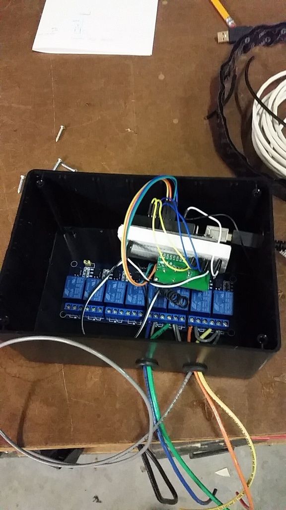
In the enclosure I put the Arduino Uno, Mini Breadboard, and the 8 channel relay board.

The schematic was backwards on the relay board, and the middle pin on the relays was the source power, and the left side of the relay was NC pin.
I'll try to draw up a schematic sometime.
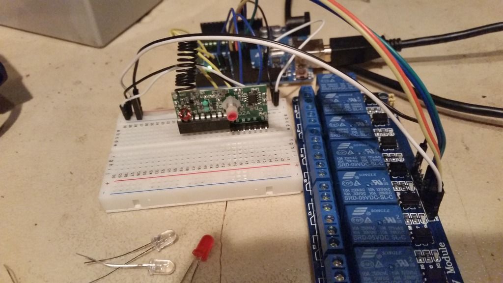
I have 4 inputs, as the receiver (remote) gives 4 outputs. The inputs go into Arduino Pins 4-7.
I have 4 outputs, just mirrors the inputs. A push of button A toggles pin 8, button B to pin 9, and so on.
The relay module I have has male pins for 5v power, ground, and 8 inputs. I just went straight from pin 9 on the Arduino to IN1 on the relay board.
I color coordinated the wires from the Arduino to the relay board to the outputs of the relay.
A) Yellow
B) Orange
C) Green
D) Blue
I took the 5v pins from the Arduino and energized the positive rail on the breadboard, and took a positive wire to the receiver, and to VCC (I think) on the relay board. Same with ground.
As far as vibration issues, I still haven't secured the battery or project enclosure in my toolbox
 , but I haven't had any issues.
Senior Member
Joined: Dec 2015
Posts: 175
Likes: 17
From: Ohio
Well thank you! Making a touch screen to control lights has been on my dream to-do list for a while now. Over the summers, I do custom electrical wiring and lighting installations on semi trailers for high school bands.
My brother got a RPi2 for Christmas, and we're planning on making a dash cam out of it that has a wifi dongle, so it will upload all the video to our server when it finds an open wifi network.
Anyway, as far as just bluetooth connectivity, I had found a bluetooth relay board a while back on ebay.
It comes with its own app from the Play store, but I think you could pretty easily make your own that follows the proper protocols.
As far as my wiring, I tried to make it plug and play.
The grey wire is the 12v wire that goes IN to the relays, And the different colors are the 4 channels I control with the key fob. Those wires go straight to the fuse block, and then to the lights. The black cable going out the side is the USB cable for the Arduino. I have that going to a 12v socket with a USB charger plugged in.
In the enclosure I put the Arduino Uno, Mini Breadboard, and the 8 channel relay board.
The schematic was backwards on the relay board, and the middle pin on the relays was the source power, and the left side of the relay was NC pin.
I'll try to draw up a schematic sometime.
I have 4 inputs, as the receiver (remote) gives 4 outputs. The inputs go into Arduino Pins 4-7.
I have 4 outputs, just mirrors the inputs. A push of button A toggles pin 8, button B to pin 9, and so on.
The relay module I have has male pins for 5v power, ground, and 8 inputs. I just went straight from pin 9 on the Arduino to IN1 on the relay board.
I color coordinated the wires from the Arduino to the relay board to the outputs of the relay.
A) Yellow
B) Orange
C) Green
D) Blue
I took the 5v pins from the Arduino and energized the positive rail on the breadboard, and took a positive wire to the receiver, and to VCC (I think) on the relay board. Same with ground.
As far as vibration issues, I still haven't secured the battery or project enclosure in my toolbox , but I haven't had any issues.
My brother got a RPi2 for Christmas, and we're planning on making a dash cam out of it that has a wifi dongle, so it will upload all the video to our server when it finds an open wifi network.
Anyway, as far as just bluetooth connectivity, I had found a bluetooth relay board a while back on ebay.
It comes with its own app from the Play store, but I think you could pretty easily make your own that follows the proper protocols.
As far as my wiring, I tried to make it plug and play.
The grey wire is the 12v wire that goes IN to the relays, And the different colors are the 4 channels I control with the key fob. Those wires go straight to the fuse block, and then to the lights. The black cable going out the side is the USB cable for the Arduino. I have that going to a 12v socket with a USB charger plugged in.
In the enclosure I put the Arduino Uno, Mini Breadboard, and the 8 channel relay board.
The schematic was backwards on the relay board, and the middle pin on the relays was the source power, and the left side of the relay was NC pin.
I'll try to draw up a schematic sometime.
I have 4 inputs, as the receiver (remote) gives 4 outputs. The inputs go into Arduino Pins 4-7.
I have 4 outputs, just mirrors the inputs. A push of button A toggles pin 8, button B to pin 9, and so on.
The relay module I have has male pins for 5v power, ground, and 8 inputs. I just went straight from pin 9 on the Arduino to IN1 on the relay board.
I color coordinated the wires from the Arduino to the relay board to the outputs of the relay.
A) Yellow
B) Orange
C) Green
D) Blue
I took the 5v pins from the Arduino and energized the positive rail on the breadboard, and took a positive wire to the receiver, and to VCC (I think) on the relay board. Same with ground.
As far as vibration issues, I still haven't secured the battery or project enclosure in my toolbox
, but I haven't had any issues.Thanks for the info. I just started a project discussion thread to get ideas and info like this, feel free to jump on over and join in.
https://www.f150forum.com/f38/sugges...d-mine-325563/
Thanks again! Look forward to the added lights in the setup.

Senior Member
Joined: Dec 2015
Posts: 175
Likes: 17
From: Ohio
I'll definitely keep you updated as I go though if you'd like.


Trending Topics
Senior Member
Joined: Jul 2015
Posts: 358
Likes: 11
From: Adamsville Tn
**I know, I know, another lighting post!**
I was poking around looking for a place to put this in case anyone wanted to see. I'm still waiting for better weather to get out and take better pictures of the light output, but this will do for now!
2 LED Cubes found for CHEAP on amazon here.
I have the lights going through an 8 channel relay board wired up to an Arduino Uno microcontroller getting signals from a 4 button key fob and 4 channel momentary receiver.
For now, I have the lights on 2 seperate channels/buttons, but will eventually combine when I get more lights to use.
There are 8 relays, and 4 buttons on the key fob, so I just pre-wired 4 toggled channels. I am using 2 for the back lights, and will use 1 for the front flood lights when I get them installed, one for bed + toolbox lights, and maybe an air compressor in the future.
Enough words, here some pictures from the night I installed them!
And all of this is completely isolated from my electrical system. I am running a dry-cell battery that we use in our robotics (works awesome!) going to a terminal block, grounding block, fuse block, 2 12v outlets, and to the black box that houses the micro-controller and relays.
Immediate future plans are to install the front flood/ fog lights, and install the bed lights. I also will be programming in a timer for the bed lights.
Somewhere in the future is a headache rack mounted solar panel, OBA (which i have), and start making more remote controlled light modules!
This was a fun project, and is ever evolving! I would love some feedback, and see some more pictures of the off road lighting installations!
 Plus Grand Daughters car is still in the way. Had to order a timing cover for her car. So looks like it will be after the first of the year before my truck gets in. Then I hope 2 days the engine is in, both front half axles are in. And I can drive a truck that has been min for 8 months.
Pete
Senior Member
Joined: Dec 2015
Posts: 175
Likes: 17
From: Ohio
Well was going to say, I'm on my way to let you hook up some for me. But 9 hours 5 minutes one way. Don't think that will work. Plus Grand Daughters car is still in the way. Had to order a timing cover for her car. So looks like it will be after the first of the year before my truck gets in. Then I hope 2 days the engine is in, both front half axles are in. And I can drive a truck that has been min for 8 months.
Pete
Plus Grand Daughters car is still in the way. Had to order a timing cover for her car. So looks like it will be after the first of the year before my truck gets in. Then I hope 2 days the engine is in, both front half axles are in. And I can drive a truck that has been min for 8 months.Pete
Thread Starter
Senior Member
Joined: Nov 2014
Posts: 152
Likes: 4
From: Stillwater, OK
Thank you sir! I love the color combo with those wheels!
Yes just like vitafortis said, it was pretty easy. I was uncomfortable tapping into my truck's electrical system, so I put a dedicated battery back there. The code is definitely not the cleanest thing in the world, but it's easy for me to read and straightforward. I will see about uploading it to our website soon.
I have a question for you if you can help. The RF Antenna on the receiver was coiled up tight when I got it, and I uncoiled it a bit before I installed in in the project enclosure. Everything was fine when I installed it in the toolbox, until I closed the toolbox lid. Now the range is down to 3 or 4 feet, instead of the 20-30 feet I get if the toolbox is open. Can I just add more wire to it? Is there a little antenna I can mount to the top of the toolbox?
Well was going to say, I'm on my way to let you hook up some for me. But 9 hours 5 minutes one way. Don't think that will work. Plus Grand Daughters car is still in the way. Had to order a timing cover for her car. So looks like it will be after the first of the year before my truck gets in. Then I hope 2 days the engine is in, both front half axles are in. And I can drive a truck that has been min for 8 months.
Pete
Plus Grand Daughters car is still in the way. Had to order a timing cover for her car. So looks like it will be after the first of the year before my truck gets in. Then I hope 2 days the engine is in, both front half axles are in. And I can drive a truck that has been min for 8 months.Pete
I have a question for you if you can help. The RF Antenna on the receiver was coiled up tight when I got it, and I uncoiled it a bit before I installed in in the project enclosure. Everything was fine when I installed it in the toolbox, until I closed the toolbox lid. Now the range is down to 3 or 4 feet, instead of the 20-30 feet I get if the toolbox is open. Can I just add more wire to it? Is there a little antenna I can mount to the top of the toolbox?