How to: Use key-less entry to turn low beams on and off
 03-14-2013, 02:11 PM
#1

What this mod does:
1.) Uses key-less entry to turn headlights on/off with lock and unlock(on your key).
2.) This mod also allows the head-lights (low-beams) to turn on when you open any door, and thus shut off when you close the door back.
Other options:
Instead of turning "low beams" on and off. You can use this mod to turn on, parking lamps/fogs/aux lights, etc. If enough members are interested in this, I will add the how to on all of these.
Why would you want to do this?
Anyone camping or working in the dark near their truck could find this beneficial. This is also fairly common among newer model vehicles.
Could help you find your vehicle in a parking garage or parking lot without activating "panic" mode.
Which trucks does this work for?
My truck is a 2003 FX4 without auto lamps. Even though some of our model years have different plugs, the wire colors should be the same. *I have not tried this mod on the trucks with auto-lamps* see below to tell which you have.
Which headlight switch do you have?
Easy, you either have DRL or you don't. If you can turn your headlight **** to the left(counter clockwise) from the off position, then you have "auto lamps". If you are like me, and you don't have DRL's, then your **** will not turn left. The last position going counter clockwise is the off setting. If you have DRL's contact me and I will try to guide you along.
Auto-lamps/DRL
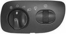
No Auto-lamps/DRL
Materials:
1.) One- 12V 30-40 Amp realy. (SPST, SPDT all work)
2.) 4- Female wire connectors or (factory relay connector)
3.) 15-20 ft. of 12-14ga. wire.
4.) 10 ft. of 18ga wire.
5.) Heat Shrink Tubing and/or electrical tape.
6.) 1- (12-14ga.) crimp wire connector. (optional)
7.) 1- Ring connector for 14ga wire.
8.) 15-20 amp fuse and connector
Tools:
1.) Flat head screwdriver (for prying)
2.) Wire cutters (or needle nose)
3.) Pliers (any size)
4.) Utility knife (optional)
Getting started!
First step: Be safe, unhook your ground terminal from the battery.
Second: Think ahead! Where are you going to mount your relay(all wires will run to and from this)? Thus I suggest to hide it under the hood to the right of the fuse box to keep it tidy.
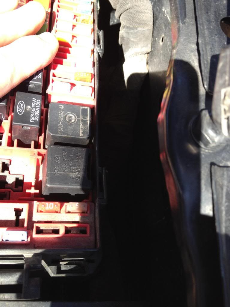
Just make sure to cover all connections so they dont ground themselves out. *Plasti-dip(the can version) makes a great insulator, so after everything is connected you can use this to cover any open connections*.
Running the Switched Turn On to the Relay.
Third:
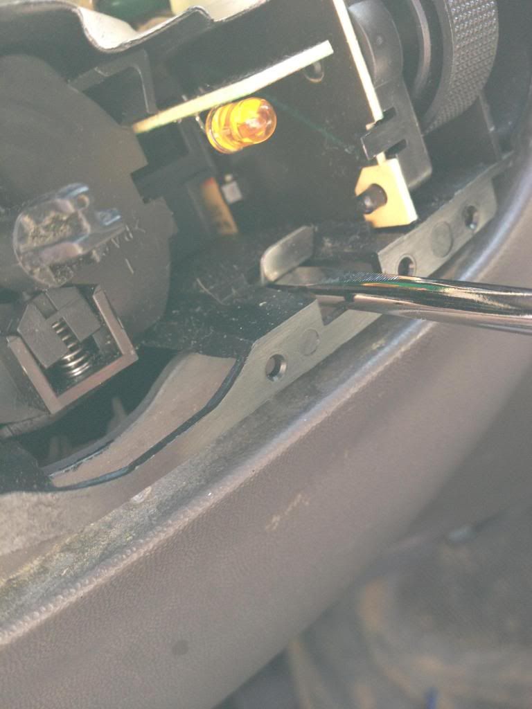
Go to the passenger side of the truck(front is easiest) and remove the interior door threshold. It should just pop off. Use a flat head with some type of cloth over it (as not to scratch it) if you cant get it by hand.
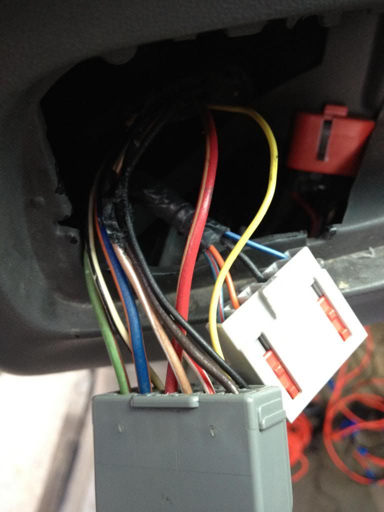
Once you have the threshold off, you will see a bundle of wire wrapped in tape.
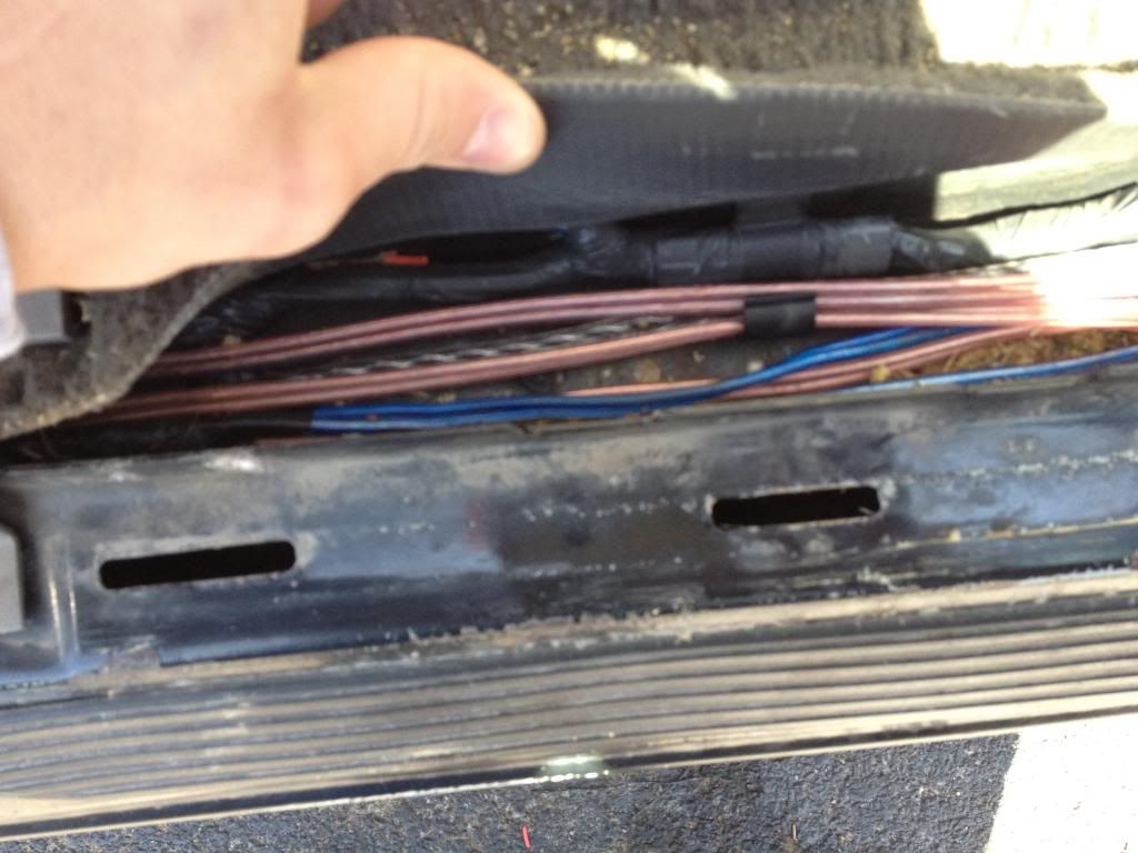
You will need to use a utility knife to remove about 6 inches tap so you can see the wires and work with the one we need.
Fourth:
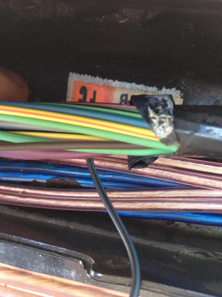
You will need to find the Black and Light Blue wire. CAUTION: There is a wire in the bundle that is also dark brown and light blue, make sure to NOT USE THIS ONE.
The correct wire should look like this:
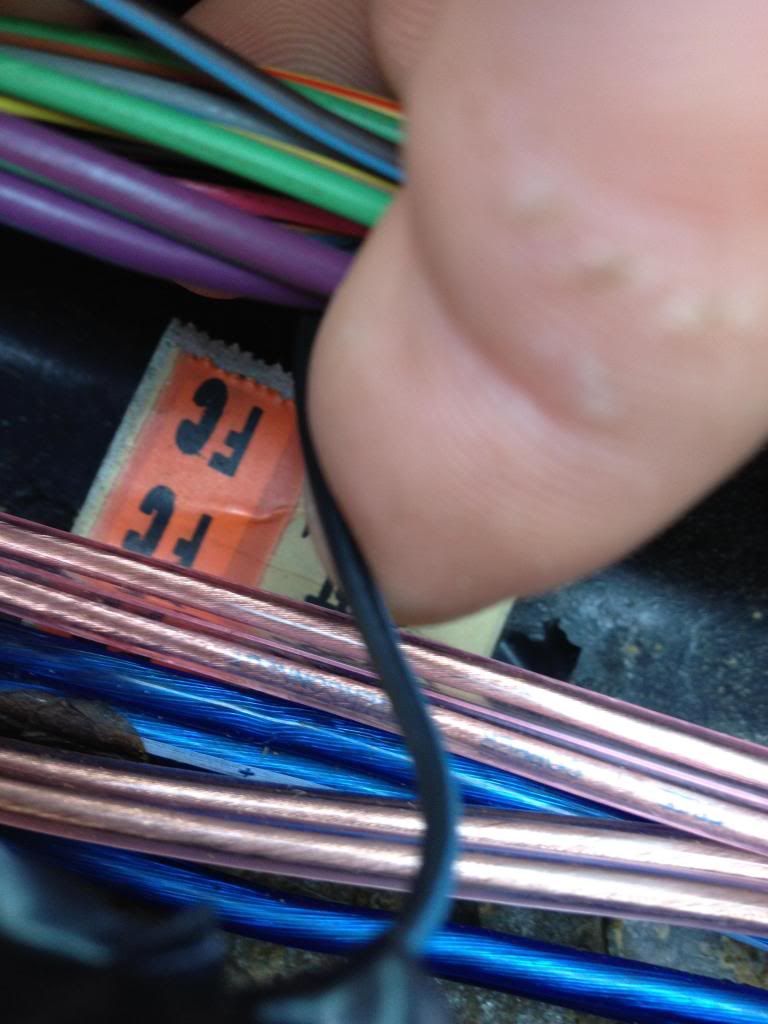
Once you locate the wire, splice into it (or use a wire crimp connector) with the 18ga. wire and run it behind the dash(or however you like) to the engine compartment where you are mounting the relay. Make sure the factory wire is still connected together, only splice into it(DONT CUT IT).
Note: You will need to run the wire through the factory firewall/plug right under the steering column.
*I have alot of accesory wires, but at this time, your install should only have the wire splice into the Black/Lght Blue wire running through the firewall.
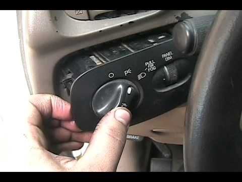
Headlamp switch removal and wiring:
Now we need to concentrate on the headlamp switch.
First: Remove the **** on the switch. (just pull slightly)
Second: Remove the outside bezel. (pull slightly or use a flat head)
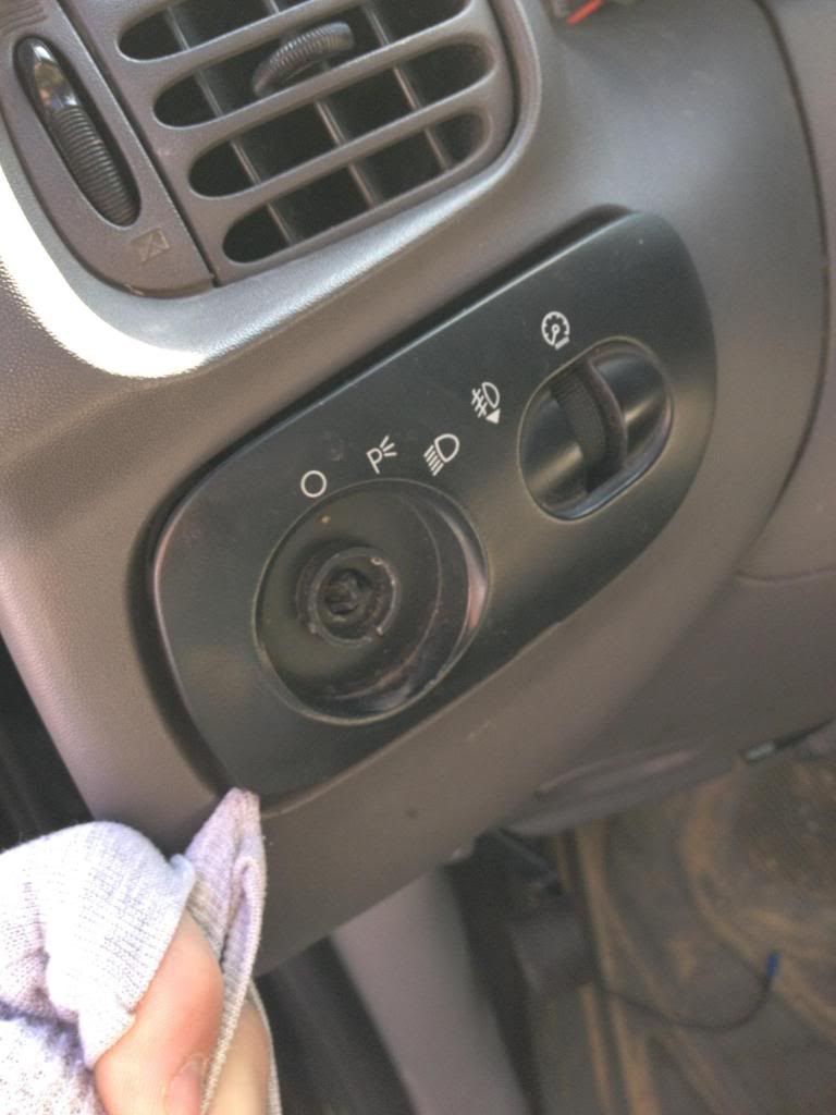
Third: Remove the Switch itself. (There are two prongs you need to lift up to remove the switch)
1.) Uses key-less entry to turn headlights on/off with lock and unlock(on your key).
Other options:
Instead of turning "low beams" on and off. You can use this mod to turn on, parking lamps/fogs/aux lights, etc. If enough members are interested in this, I will add the how to on all of these.
Why would you want to do this?
Anyone camping or working in the dark near their truck could find this beneficial. This is also fairly common among newer model vehicles.
Could help you find your vehicle in a parking garage or parking lot without activating "panic" mode.
Which trucks does this work for?
My truck is a 2003 FX4 without auto lamps. Even though some of our model years have different plugs, the wire colors should be the same. *I have not tried this mod on the trucks with auto-lamps* see below to tell which you have.
Which headlight switch do you have?
Easy, you either have DRL or you don't. If you can turn your headlight **** to the left(counter clockwise) from the off position, then you have "auto lamps". If you are like me, and you don't have DRL's, then your **** will not turn left. The last position going counter clockwise is the off setting. If you have DRL's contact me and I will try to guide you along.
Auto-lamps/DRL
No Auto-lamps/DRL
Materials:
1.) One- 12V 30-40 Amp realy. (SPST, SPDT all work)
2.) 4- Female wire connectors or (factory relay connector)
3.) 15-20 ft. of 12-14ga. wire.
4.) 10 ft. of 18ga wire.
5.) Heat Shrink Tubing and/or electrical tape.
6.) 1- (12-14ga.) crimp wire connector. (optional)
7.) 1- Ring connector for 14ga wire.
8.) 15-20 amp fuse and connector
Tools:
1.) Flat head screwdriver (for prying)
2.) Wire cutters (or needle nose)
3.) Pliers (any size)
4.) Utility knife (optional)
Getting started!
First step: Be safe, unhook your ground terminal from the battery.
Second: Think ahead! Where are you going to mount your relay(all wires will run to and from this)? Thus I suggest to hide it under the hood to the right of the fuse box to keep it tidy.
Just make sure to cover all connections so they dont ground themselves out. *Plasti-dip(the can version) makes a great insulator, so after everything is connected you can use this to cover any open connections*.
Running the Switched Turn On to the Relay.
Third:
Go to the passenger side of the truck(front is easiest) and remove the interior door threshold. It should just pop off. Use a flat head with some type of cloth over it (as not to scratch it) if you cant get it by hand.
Once you have the threshold off, you will see a bundle of wire wrapped in tape.
You will need to use a utility knife to remove about 6 inches tap so you can see the wires and work with the one we need.
Fourth:
You will need to find the Black and Light Blue wire. CAUTION: There is a wire in the bundle that is also dark brown and light blue, make sure to NOT USE THIS ONE.
The correct wire should look like this:
Once you locate the wire, splice into it (or use a wire crimp connector) with the 18ga. wire and run it behind the dash(or however you like) to the engine compartment where you are mounting the relay. Make sure the factory wire is still connected together, only splice into it(DONT CUT IT).
Note: You will need to run the wire through the factory firewall/plug right under the steering column.
*I have alot of accesory wires, but at this time, your install should only have the wire splice into the Black/Lght Blue wire running through the firewall.
Headlamp switch removal and wiring:
Now we need to concentrate on the headlamp switch.
First: Remove the **** on the switch. (just pull slightly)
Second: Remove the outside bezel. (pull slightly or use a flat head)
Third: Remove the Switch itself. (There are two prongs you need to lift up to remove the switch)
Last edited by ibd2328; 03-14-2013 at 03:38 PM.
 03-14-2013, 02:11 PM
#2
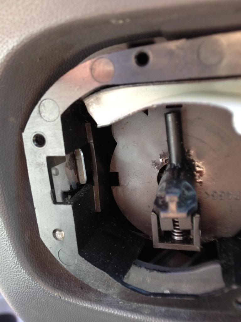
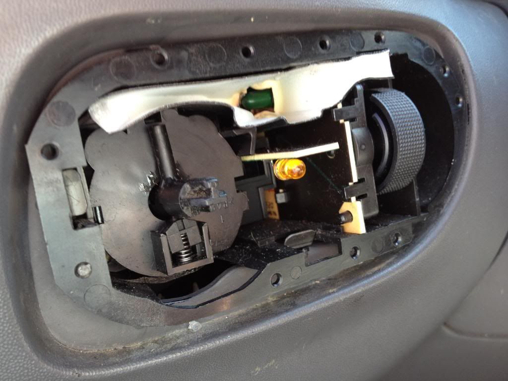
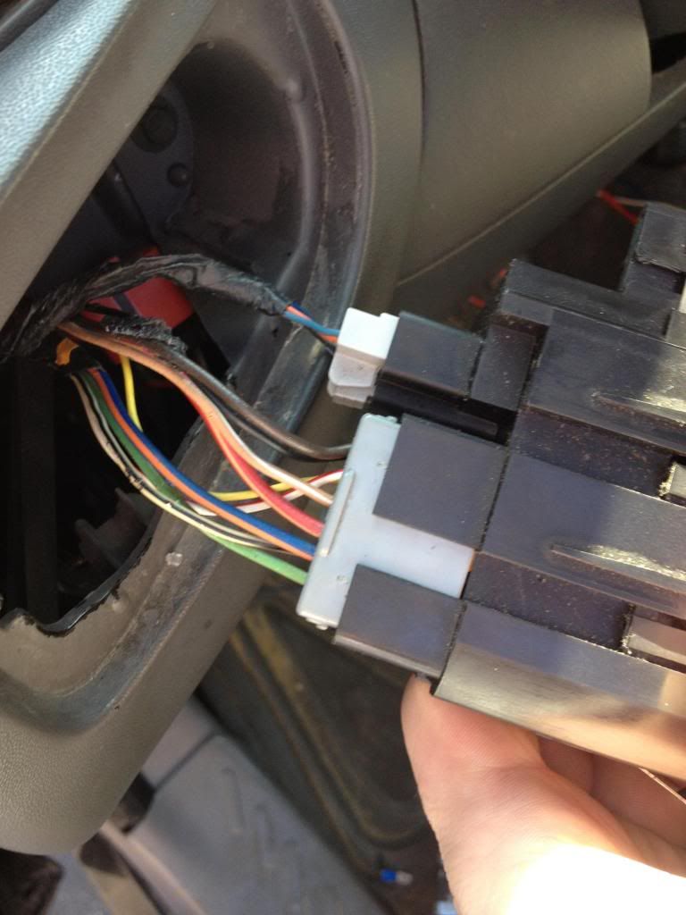
Once you remove the switch platform itself, you will see two connectors on it.
We will only be using the larger plug (the one with the most pincs). The smaller plug is for dash illuminating, etc.
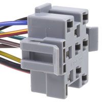
Your plug should look like either of these two, depending on model.
You may need to remove some of the tape on the wiring to do the next few steps.
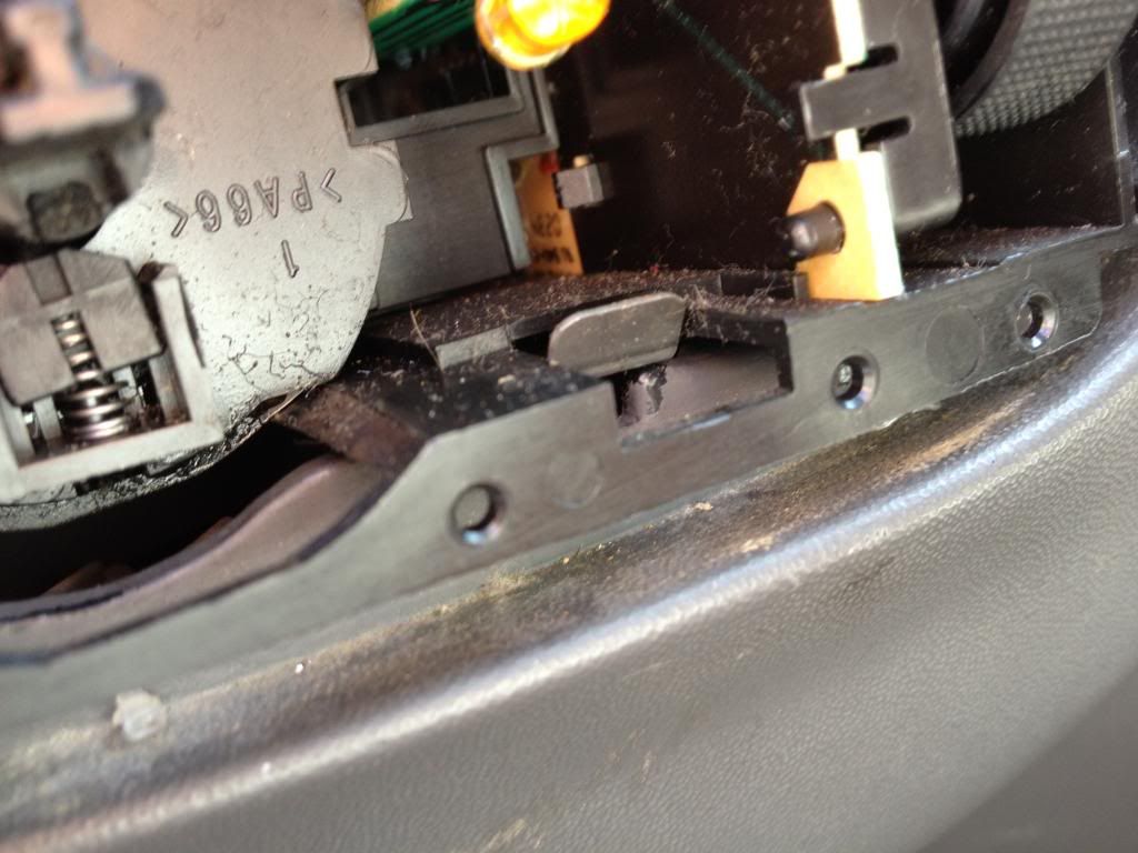
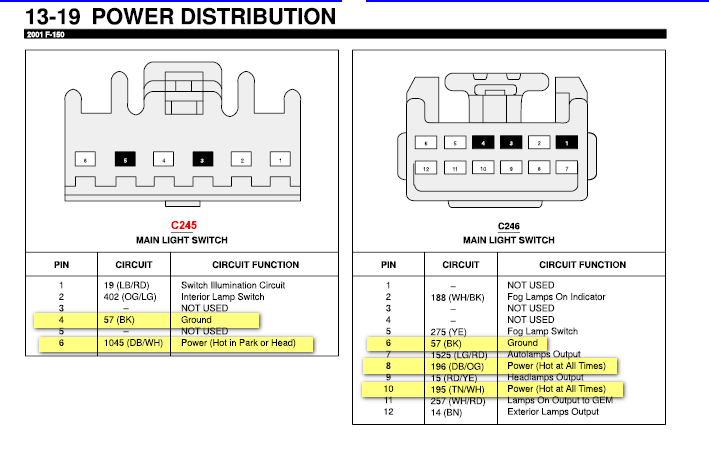
If you have the square plug. (shown in the schematic) Locate pin #9. On both plugs its should be the Red and Yellow wire.
We will now need to splice into this wire(Red and Yellow) using 12-14ga wire. Make sure to not cut the wire in half, only splice into it. Once you get the splice done, run this wire through the firewall again to the relay outside. We will connect the relay in just a moment. (NOTE: I used a 10amp diode to make sure to not short anything out. I recommend this, just make sure the cathode part is the one spliced into the Red/Yellow wire). The diode only lets power flow in one direction(whichever direction the cathode is facing)
Running the ground and power wire for relay:
Right now you should have two wires at the relay(not attached yet). The 18ga wire from the Black/Lght Blue wire, and the 12ga wire from the Red/Yellow wire.
We now need to run ground and power wires to the relay location.
Power:
Run another strand of the 12ga wire from the (+) on the battery (across the engine bay) to the relay. Remember to use a fuse(20 amp) within 18" of the battery.
Ground:
Run a strand of 16-18ga wire from any ground location (I used the battery (-)) to the relay.
You are now done running wires, all we do is have to attach the wires to the proper location on the relay. To attach the wires, use either the appropriate harness or 1/4" female connectors.
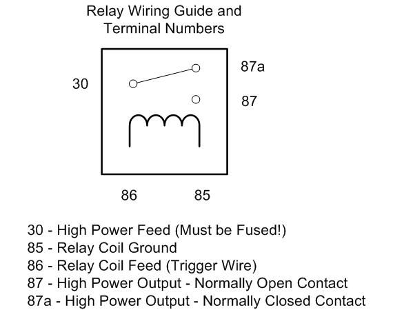
Depending on the type of relay you choose, these locations could vary. I used a 5-pin SPST relay (single pole, single throw). Don't get confused, the SPST just means the relay is normally open when the Black/Blue wire isn't on. (It doesn't give an option for normally closed like the bosch relay's).
For general (SPST) cheap relays. Reguardless of 5pin of 4pin.
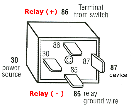
86 = Switched Turn On (16-18 ga wire from the Black/Light Blue wire to this pin)
85= Ground(16-18ga wire from this pin to any ground location)
30= Power (12ga wire "fused" from battery to this pin)
87= Output (12ga wire from the Red/Yellow wire to this pin).
87a = N/A
Last edited by ibd2328; 03-14-2013 at 02:14 PM.
03-14-2013, 02:12 PM
#3
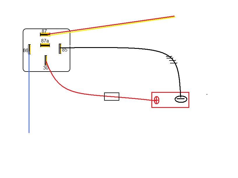
For Bosch type relays SPDT
The same schematics works, just leave pin 87a open and use a diode. (more complicated)
Now tidy up the wiring with zip ties.
Attach the ground back to the battery.
Replace the threshold and headlight switch in reverse order.
Try out your new mod.
The same schematics works, just leave pin 87a open and use a diode. (more complicated)
Now tidy up the wiring with zip ties.
Attach the ground back to the battery.
Replace the threshold and headlight switch in reverse order.
Try out your new mod.
 03-14-2013, 02:56 PM
#5
You will need to pull your radio out to pull them through, and then run them down by the radio to the firewall
Trending Topics
03-14-2013, 03:18 PM
#8
If your parking lights are wired on the same circuit/parallel with the fogs, then your parking lights will come on also.
A way to get around that is.
Run a 10amp diode(1.99 cents) from the RED/Yellow wire to the Solid Yellow wire. This allows the fogs to come on when the low beams are on(make sure the anode is on the RED/Yellow wire). Now you want to run a diode from the parking lights signal to the fogs. (make sure the anode is connected to the parking lights). That will prevent the parking lights to come on when doing the mod.
*A diode only lets current flow in one direction, towards the cathode*
03-14-2013, 03:25 PM
#10
Then don't use the Red/Yellow wire at all.
Do the following:
1) Splice the wire from pin#87 on the relay to the Solid Yellow Wire on the plug(pin #5 on the plug).
If your fogs come on with your parking lamps, then this Schematic will use your fogs and parking lights in place of the low beams. So your parking lamps/fogs will come on when you use your keyless entry.