How to: Reverse lights with internal/external aux switches.
 03-08-2013, 07:03 PM
#1

I know there are a few write ups on how to wire up a relay using an aux switch, however, I wanted to do a write up on using 3 different means of turn on leads ( 1. Switch in the cab, 2. Switch on the tow harness bracket, 3. using reverse as a lead). There are different ways to doing this, but this one fit my needs the best.
First: Realize there are lots of different configurations for this, I will try to name a few of the most popular setups before I get into the "how to" part. Choose which configuration fits your needs. * I won't name all of them* but you should be able to figure this out once you read the entire post. If you get confused, back track yourself and review how each relay works separately. Here are some of the basics and additional info:
https://www.f150forum.com/f75/auxila...cluded-148074/
Keeping every switch on a separate circuit (RECOMMENDED)
If you want to keep everything switch from effecting and turning off the other, you will need 3 relays (my way to keep power efficient). By keeping the switches and circuits separate you won't have to worry about turning your inside switch on and your factory reverse lights coming on. Another scenario which could occur if you dont keep them separate is: you could leave your inside switch off(in the cab) and your switch on the tow harness bracket will not work, so your lights will not work via the outside switch.
Keeping Reverse separate, but allowing your rear switch to have priority over the cab switch. *This is the way I decided to go.* If I want to go behind my truck with the truck not on and flip my lights on, they will work independently. I like this circuit since I do alot of camping and unloading at night. Note: The switch on the rear will have the full amperage of the lights going to it, so make sure to get a 30amp external switch. The switch in the cab will only serve as a remote turn on lead for the first relay.
There are way too many configurations to name, but another one that could be beneficial is adding an aux switch to be able to turn off your back up lights when in reverse. I wont go into detail on this one, as I chose to not go this route. However, here is another option to show you similarities and differences.
The route I chose and will be showing you how to:
Keeping Reverse separate, but allowing your rear switch to have priority over the cab switch.
For my setup, I will be using two 30-amp heavy duty relays. The relays I chose are 5pin and have two power outlets(pins 87, 87a). Some relays can be used outside, check with your parts store and make sure they are waterproof before installing anything on the exterior of your truck. If you can't find any waterproof relays, you can always hook them up in the cab and run wires to the sources(takes more wire obviously). Or waterproof them with plasti-dip as another member has already suggested.
Depending on your lights wattage, your relays amperage may vary.... See this post for more info on wattage/amps/volts. Your wiring needs to be of appropriate gauge as well. For almost all off-road lights/fog lights 14 gauge wire will be sufficient. (conditional on how far they are from your battery source).
Materials:
1) One set of back up lights (fog lights)
2) 1 12V- 30amp exterior aux switch
3) 1 12V- Interior switch
4) Three 30-Amp Exterior Relays (5 pin) and one-5-10amp fuse
5) Three 30-amp fuse's and holders and one 5-10amp fuse holder.
6) Depending on your configuration and relay positioning.. around 50-75 feet of 14 gauge wire. *I bought 3 different colors of wire for this how to, it makes wiring much easier to keep up with.
Red- All 12V fused power (to relays) and turn on leads
Yellow - Power to Lamps
Black - Ground
7) 16 - 1/4" female connectors.
8) 2- Self taping screws if you are doing the exterior mounted relays.
Tools:
1) Wire Cutters/Need Nose plier
2) Soldering iron
3) Electrical Tape
4) Drill (for self taping screws), mounting lights, and mounting exterior aux. switch.
Positioning hardware(Lights, Relays, Switches)
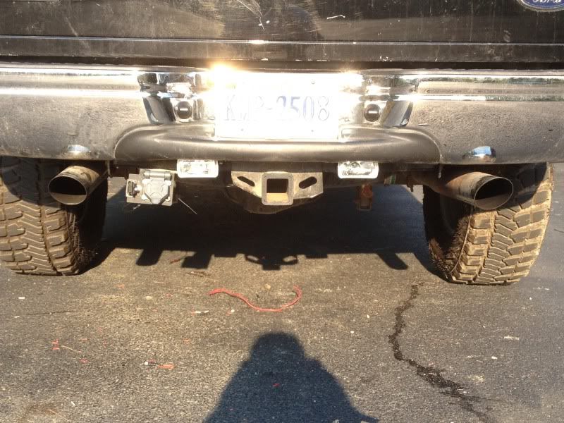
First: Position your lights where you would like them on the back of the truck. I actually tack welded mine to the steel towing bar. I wanted to position them so I could fold them upwards and be out of sight from people, and also keep the lens from getting damaged driving.
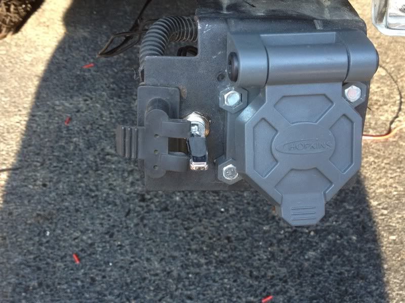
Second: Mount your External 30-amp Switch on the tow harness bracket.
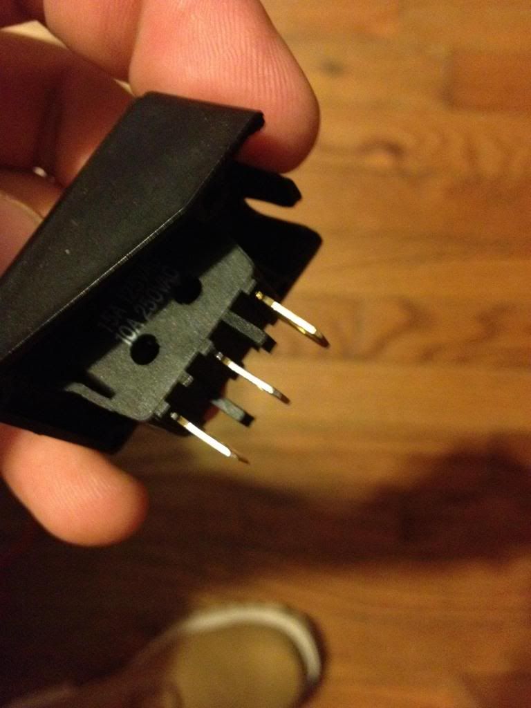
Third: Mount your interior switch whenever you would like. (Leave access, we will need to get to this in a moment). Should look like this with 2 or 3 pins.
Fourth: Mount your two relays whenever you would like(closer to the lights, the easier the wiring).
Each should look like this.
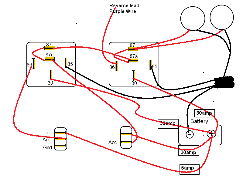
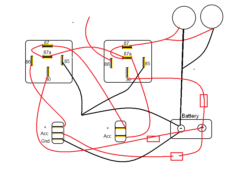
Before running wires, here is a review on what wires go where.
-a standard bosch-style relay will have 4 or 5 numbered leads (30, 85, 86, 87, and sometimes 87a). why they picked those numbers, I have no clue; but I can tell what they hook up to.
-30 = constant [positive (+)] power (usually wired directly to car battery)
-85 = coil ground (wired to the negative (-) battery terminal or any grounded metal panel in the car)
-86 = coil power (wired to the control source. could be a switch, or it could be the car's IGN or ACC circuit.)
-87 = switched [positive (+)] power output. (when the relay coil is powered, lead/pin 87 is connected to lead/pin 30)
-87a = [on 5 lead/pin relays only] this lead/pin is connected to lead/pin 30 when the coil is NOT powered.
Finally: Time to run the wires, and figure out how this configuration works.
*DISCONNECT THE GROUND ON YOUR BATTERY BEFORE PROCEEDING*
For the following steps I will relate and reference the picture below.
Note: Realy #1 is on left, Realy #2 is on right.
This particular part will relate to all "FUSED" wires from the battery (4), and all wires running to and from the aux switches.
1) Run two separate 14ga "30 amp fused" wires from the battery to the #30 pin on each relay.
2) Next we will run another 14ga. "30 amp FUSED" wire from the battery to the #ACC point on the external aux. switch(Once of the tow harness).
Once that is done, on the same external aux. switch run another strand of 14ga. wire from the + on the switch to #87a or#87 on the first relay.
3) Now run a strand of 14-16ga wire from the battery "5amp FUSED" to the #acc pin on the internal aux switch(one in the cab). Then, on the same internal switch run another strand of 14ga. wire from the + on the switch to pin #86 on relay number 1.
*If your interior switch has an light (an extra pin/ ground) then run a wire from the pin labeled ground to any ground in the cab of your truck. We are now done wiring in switches and fuses.
Wiring all the pins on the relay to the lights and other locations:
Concentration on relay #1:
We should already have pin #30, 87a, and #86 wired in.
1) Now run another piece of "Black" (doesn't matter what color) 14ga wire from pin #85 to a solid ground
2) *****Note: Pin #87 and #87a will have two wires attached each, so dont crimp until done.
The only pin left untouched on relay #1 is pin #87 (both 87 and 87a conduce power) . These pins are the output of the relay (up to 30amps).
So run another piece of 14ga wire from pin #87 on relay #1 to, pin #87a on relay # 2.
3) Run a very short strand from (87 to 87a) to help the relay's efficiency.
*relay #1 is now finished*
Concentration on Relay #2
The only pin on relay#2 covered right now should be, pin #30 and #87a.
1) Run 14ga. wire from pin #85 to a solid ground.
2) Now we need to get into our trailer harness and find the purple wire. We will tap into that wire and run a short strand of 14ga. wire to pin #86 on relay #2.
3) *****Note: Pin #87 and #87a will have two wires attached each, so dont crimp until done.
Run a short strand of 14ga from pin #87 to #87a (pin #87a should already have a wire running from pin #87 on relay #1).
Now fore the wires on the lights
Finally, wire both positive leads of the lights to pin #87 on relay #2.
That completes all the relay wiring. Now ground the lights to an appropriate location. Both lights need to be grounded. (doesn't all have to be the same spot).
Now, replace the (-) terminal on the battery and try out your work.
Turned on without reverse.
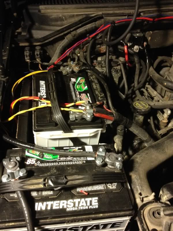
I hid my fuses to side of the battery.
First: Realize there are lots of different configurations for this, I will try to name a few of the most popular setups before I get into the "how to" part. Choose which configuration fits your needs. * I won't name all of them* but you should be able to figure this out once you read the entire post. If you get confused, back track yourself and review how each relay works separately. Here are some of the basics and additional info:
https://www.f150forum.com/f75/auxila...cluded-148074/
Keeping every switch on a separate circuit (RECOMMENDED)
If you want to keep everything switch from effecting and turning off the other, you will need 3 relays (my way to keep power efficient). By keeping the switches and circuits separate you won't have to worry about turning your inside switch on and your factory reverse lights coming on. Another scenario which could occur if you dont keep them separate is: you could leave your inside switch off(in the cab) and your switch on the tow harness bracket will not work, so your lights will not work via the outside switch.
Keeping Reverse separate, but allowing your rear switch to have priority over the cab switch. *This is the way I decided to go.* If I want to go behind my truck with the truck not on and flip my lights on, they will work independently. I like this circuit since I do alot of camping and unloading at night. Note: The switch on the rear will have the full amperage of the lights going to it, so make sure to get a 30amp external switch. The switch in the cab will only serve as a remote turn on lead for the first relay.
There are way too many configurations to name, but another one that could be beneficial is adding an aux switch to be able to turn off your back up lights when in reverse. I wont go into detail on this one, as I chose to not go this route. However, here is another option to show you similarities and differences.
The route I chose and will be showing you how to:
Keeping Reverse separate, but allowing your rear switch to have priority over the cab switch.
For my setup, I will be using two 30-amp heavy duty relays. The relays I chose are 5pin and have two power outlets(pins 87, 87a). Some relays can be used outside, check with your parts store and make sure they are waterproof before installing anything on the exterior of your truck. If you can't find any waterproof relays, you can always hook them up in the cab and run wires to the sources(takes more wire obviously). Or waterproof them with plasti-dip as another member has already suggested.
Depending on your lights wattage, your relays amperage may vary.... See this post for more info on wattage/amps/volts. Your wiring needs to be of appropriate gauge as well. For almost all off-road lights/fog lights 14 gauge wire will be sufficient. (conditional on how far they are from your battery source).
Materials:
1) One set of back up lights (fog lights)
2) 1 12V- 30amp exterior aux switch
3) 1 12V- Interior switch
4) Three 30-Amp Exterior Relays (5 pin) and one-5-10amp fuse
5) Three 30-amp fuse's and holders and one 5-10amp fuse holder.
6) Depending on your configuration and relay positioning.. around 50-75 feet of 14 gauge wire. *I bought 3 different colors of wire for this how to, it makes wiring much easier to keep up with.
Red- All 12V fused power (to relays) and turn on leads
Yellow - Power to Lamps
Black - Ground
7) 16 - 1/4" female connectors.
8) 2- Self taping screws if you are doing the exterior mounted relays.
Tools:
1) Wire Cutters/Need Nose plier
2) Soldering iron
3) Electrical Tape
4) Drill (for self taping screws), mounting lights, and mounting exterior aux. switch.
Positioning hardware(Lights, Relays, Switches)
First: Position your lights where you would like them on the back of the truck. I actually tack welded mine to the steel towing bar. I wanted to position them so I could fold them upwards and be out of sight from people, and also keep the lens from getting damaged driving.
Second: Mount your External 30-amp Switch on the tow harness bracket.
Third: Mount your interior switch whenever you would like. (Leave access, we will need to get to this in a moment). Should look like this with 2 or 3 pins.
Fourth: Mount your two relays whenever you would like(closer to the lights, the easier the wiring).
Each should look like this.
Before running wires, here is a review on what wires go where.
-a standard bosch-style relay will have 4 or 5 numbered leads (30, 85, 86, 87, and sometimes 87a). why they picked those numbers, I have no clue; but I can tell what they hook up to.
-30 = constant [positive (+)] power (usually wired directly to car battery)
-85 = coil ground (wired to the negative (-) battery terminal or any grounded metal panel in the car)
-86 = coil power (wired to the control source. could be a switch, or it could be the car's IGN or ACC circuit.)
-87 = switched [positive (+)] power output. (when the relay coil is powered, lead/pin 87 is connected to lead/pin 30)
-87a = [on 5 lead/pin relays only] this lead/pin is connected to lead/pin 30 when the coil is NOT powered.
Finally: Time to run the wires, and figure out how this configuration works.
*DISCONNECT THE GROUND ON YOUR BATTERY BEFORE PROCEEDING*
For the following steps I will relate and reference the picture below.
Note: Realy #1 is on left, Realy #2 is on right.
This particular part will relate to all "FUSED" wires from the battery (4), and all wires running to and from the aux switches.
1) Run two separate 14ga "30 amp fused" wires from the battery to the #30 pin on each relay.
2) Next we will run another 14ga. "30 amp FUSED" wire from the battery to the #ACC point on the external aux. switch(Once of the tow harness).
Once that is done, on the same external aux. switch run another strand of 14ga. wire from the + on the switch to #87a or#87 on the first relay.
3) Now run a strand of 14-16ga wire from the battery "5amp FUSED" to the #acc pin on the internal aux switch(one in the cab). Then, on the same internal switch run another strand of 14ga. wire from the + on the switch to pin #86 on relay number 1.
*If your interior switch has an light (an extra pin/ ground) then run a wire from the pin labeled ground to any ground in the cab of your truck. We are now done wiring in switches and fuses.
Wiring all the pins on the relay to the lights and other locations:
Concentration on relay #1:
We should already have pin #30, 87a, and #86 wired in.
1) Now run another piece of "Black" (doesn't matter what color) 14ga wire from pin #85 to a solid ground
2) *****Note: Pin #87 and #87a will have two wires attached each, so dont crimp until done.
The only pin left untouched on relay #1 is pin #87 (both 87 and 87a conduce power) . These pins are the output of the relay (up to 30amps).
So run another piece of 14ga wire from pin #87 on relay #1 to, pin #87a on relay # 2.
3) Run a very short strand from (87 to 87a) to help the relay's efficiency.
*relay #1 is now finished*
Concentration on Relay #2
The only pin on relay#2 covered right now should be, pin #30 and #87a.
1) Run 14ga. wire from pin #85 to a solid ground.
2) Now we need to get into our trailer harness and find the purple wire. We will tap into that wire and run a short strand of 14ga. wire to pin #86 on relay #2.
3) *****Note: Pin #87 and #87a will have two wires attached each, so dont crimp until done.
Run a short strand of 14ga from pin #87 to #87a (pin #87a should already have a wire running from pin #87 on relay #1).
Now fore the wires on the lights
Finally, wire both positive leads of the lights to pin #87 on relay #2.
That completes all the relay wiring. Now ground the lights to an appropriate location. Both lights need to be grounded. (doesn't all have to be the same spot).
Now, replace the (-) terminal on the battery and try out your work.
Turned on without reverse.
I hid my fuses to side of the battery.
 03-08-2013, 11:23 PM
#2
Senior Member

Great write up. I just started doing my reverse lights last weekend, and I couldn't find a way to do wire it so it comes on with a switch and on when I put the truck in reverse. Thanks
04-12-2013, 11:42 PM
#5

I'm curious as to why you didn't use a single fused line to feed pin 30 on both relays. I'll be installing 2 LED backup lights on my '09 XLT. The lights are 10W each so I think I can use 18 gauge wire and all 5A fuses?
04-13-2013, 03:33 AM
#6
The back of the box will tell you how many mAmps or Amps it will pull. Most Leds pull less than a single amp. So you can practically wire them to anything! Mine are halogens and pull quite a few amps, they are 75watts.
Trending Topics
04-13-2013, 11:48 AM
#8
Originally Posted by Itat
Agreed, if you're using halogens you'll be drawing a lot more amps.
In my case with LEDs, is there any reason I couldn't feed both relays (pin 30) with a single line with a 5A fuse?
In my case with LEDs, is there any reason I couldn't feed both relays (pin 30) with a single line with a 5A fuse?
The following users liked this post:
Itat (04-13-2013)