
Setting up to flat tow F-150 behind a motorhome
 08-18-2013, 07:00 PM
#1
Senior Member
Thread Starter

I recently finished modding my new 2013 F-150 FX4 to be flat towed as a dinghy behind a motorhome. The basic idea is to turn the truck into a trailer, which means adding a base plate to hook up a tow bar, adding a way to control the tail lights, adding a braking system, and wiring it all together.
Major Components
Vehicle: 2013 F-150 FX4
Base Plate: Blue Ox BX2606
Tow Bar Adapter: Roadmaster 031
Lighting Kit: Hopkins 56000 Towed Vehicle Wiring Kit
Braking System: US Gear Unified Tow Brake
Wiring Kit: Hopkins 47155 4 Wire Flat to 6 Pole Round
The work can be broken down into several phases:
Major Components
Vehicle: 2013 F-150 FX4
Base Plate: Blue Ox BX2606
Tow Bar Adapter: Roadmaster 031
Lighting Kit: Hopkins 56000 Towed Vehicle Wiring Kit
Braking System: US Gear Unified Tow Brake
Wiring Kit: Hopkins 47155 4 Wire Flat to 6 Pole Round
The work can be broken down into several phases:
- Phase 1: Install Blue Ox BX2606 Base Plate
- Phase 2: Modify Roadmaster Tow Bar
- Phase 3: Install Hoppy 56000 Tail Light Wiring Kit
- Phase 4: Install US Gear Unified Tow Brake
- Phase 5: Wire it all together
 08-18-2013, 07:02 PM
#2
Senior Member
Thread Starter
Phase 1: Install Blue Ox BX2606 Base Plate
The Blue Ox BX2606 base plate is applicable to many late-model F-150s. The brackets mount in place of the front tow hooks. While the instructions state that it may require slight trimming to the front fascia, no trimming at all was required on my 2013 FX4. The brackets include removable twist-lock tabs for an unobtrusive look when not towing.
I was a bit concerned whether this base plate would fit my '13 FX4. The Blue Ox site says that it's for the XL, STX, XLT, and Harley Davidson models without EcoBoost. They don't have a specific listing for the FX4. Furthermore, one site (etrailer.com) had a note in the description that it would not fit an FX4. (I wrote to them asking about it, and they replied that they did not know why the comment was there. I now see that they have removed the comment, and it now says it's for all '11 to '13 models except EcoBoost, King Ranch, and Raptor. Had the listing said that a month ago, I wouldn't have been concerned.) I did end up writing to Blue Ox, and they assured me that the BX2606 base plate is the right one for my truck.
The base plate installation is rather straightforward, following the Blue Ox instructions. I did make a few slight deviations, which I'll detail below.
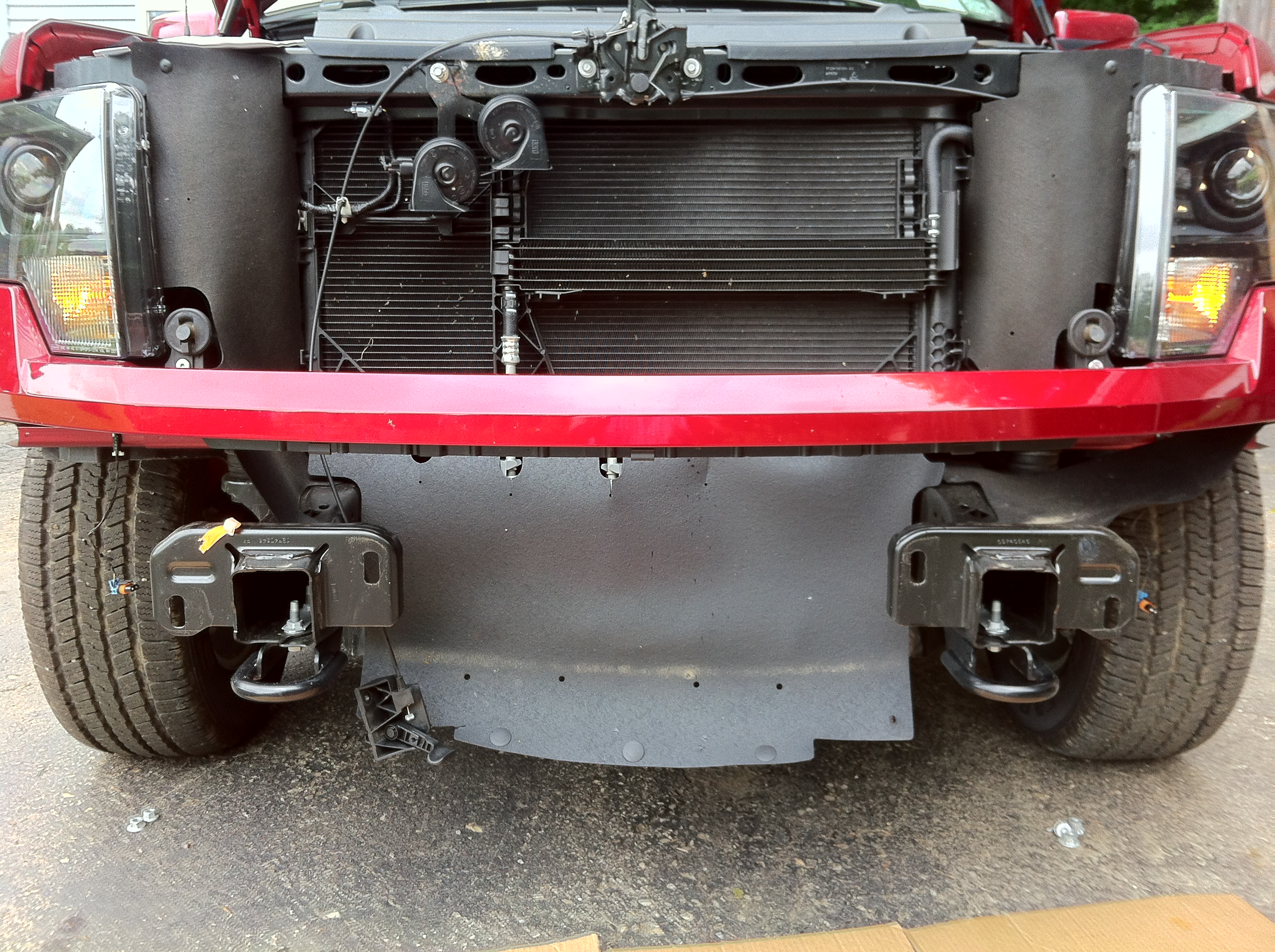
Installation starts by removing the bumper. Besides the list of tools described in the installation instructions, an air ratchet is useful to really speed things up (but nothing requires the extra power of an air impact gun.) Based on a suggestion by ron1947, I removed the air dam first. A deep 15mm socket made quick work of this. This made it easier to reach the bumper mounting bolts. The instructions call for a 21mm socket for the bumper bolts, but all of my set stop at 19mm - a 13/16 socket was a bit snug, but worked well on the bumper bolts. A minor glitch is that the hood latch is mounted to the bumper, with no mention of that in the installation instructions. I first attempted to release the cable from the latch. While it looked like it should be an easy thing to do, I had no success. So I just unbolted the latch from the bumper (10mm socket.)
Here's what the truck looks like with the hood open and without the bumper:
The air dam bolts onto a pair of studs threaded into spring clip nuts. The tow bar brackets are larger than the tow hooks, and the rear bracket bolt uses the same frame hole as the air dam. So the spring clip nuts must be removed, and according to the installation instructions, the air dam is not reinstalled.
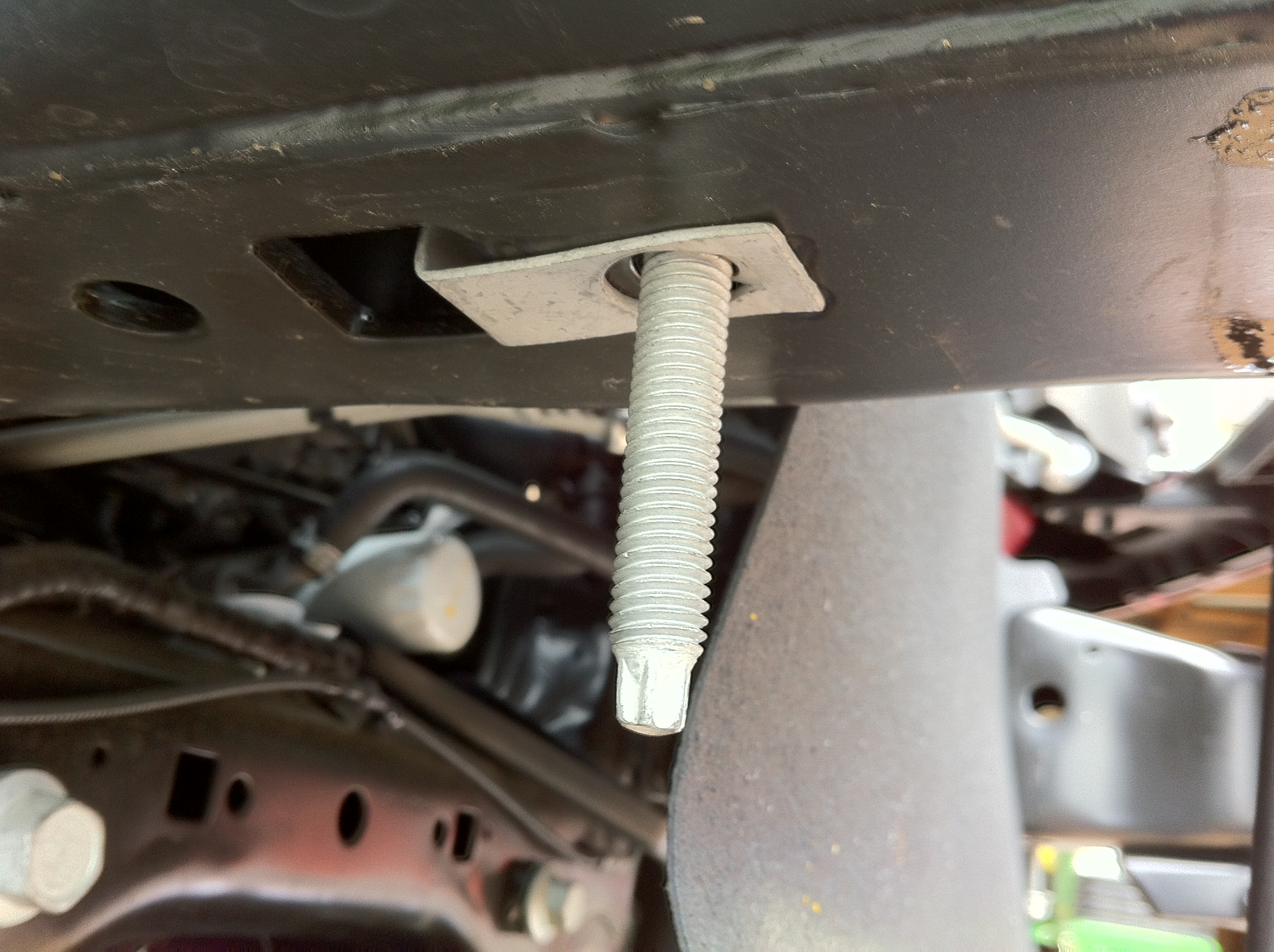
But I like the idea of having the air dam in place, so I followed a tip gleaned from a RoadMaster base plate installation guide and mounted the air dam in an alternate location. The studs have a Torx driver profile on the end. I didn't have a matching socket, so I just used a pair of locking pliers to clamp onto the Torx splines and rotate out the stud. With the stud out, the spring clip on the nut is easy to remove. After removing the spring clip nuts, I turned them 180 degrees and reinserted them in the next set of holes toward the back of the truck, and reinstalled the studs.
This is the factory location of the air dam mounting studs: (passenger side, front of vehicle to the right)
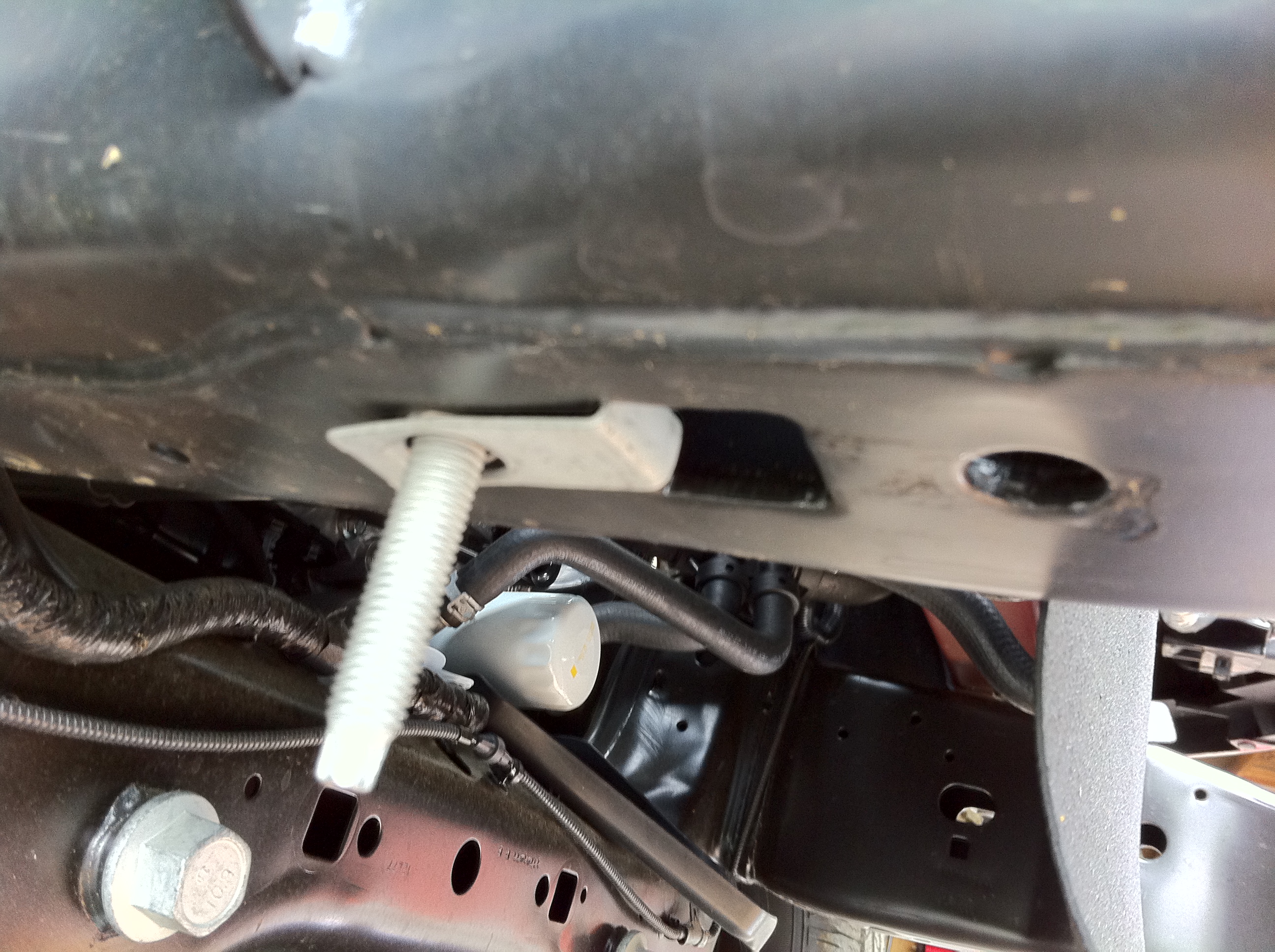
And this is where I relocated them: (passenger side, front of vehicle to the right)
Removing the tow hooks and bolting the base plate brackets in place was very straightforward, and is covered very well by the installation instructions. It involves drilling a couple holes, which the instructions indicate should be 17/32" diameter. I used a 1/2" bit (16/32") and had no issues fitting the bolts through the holes.
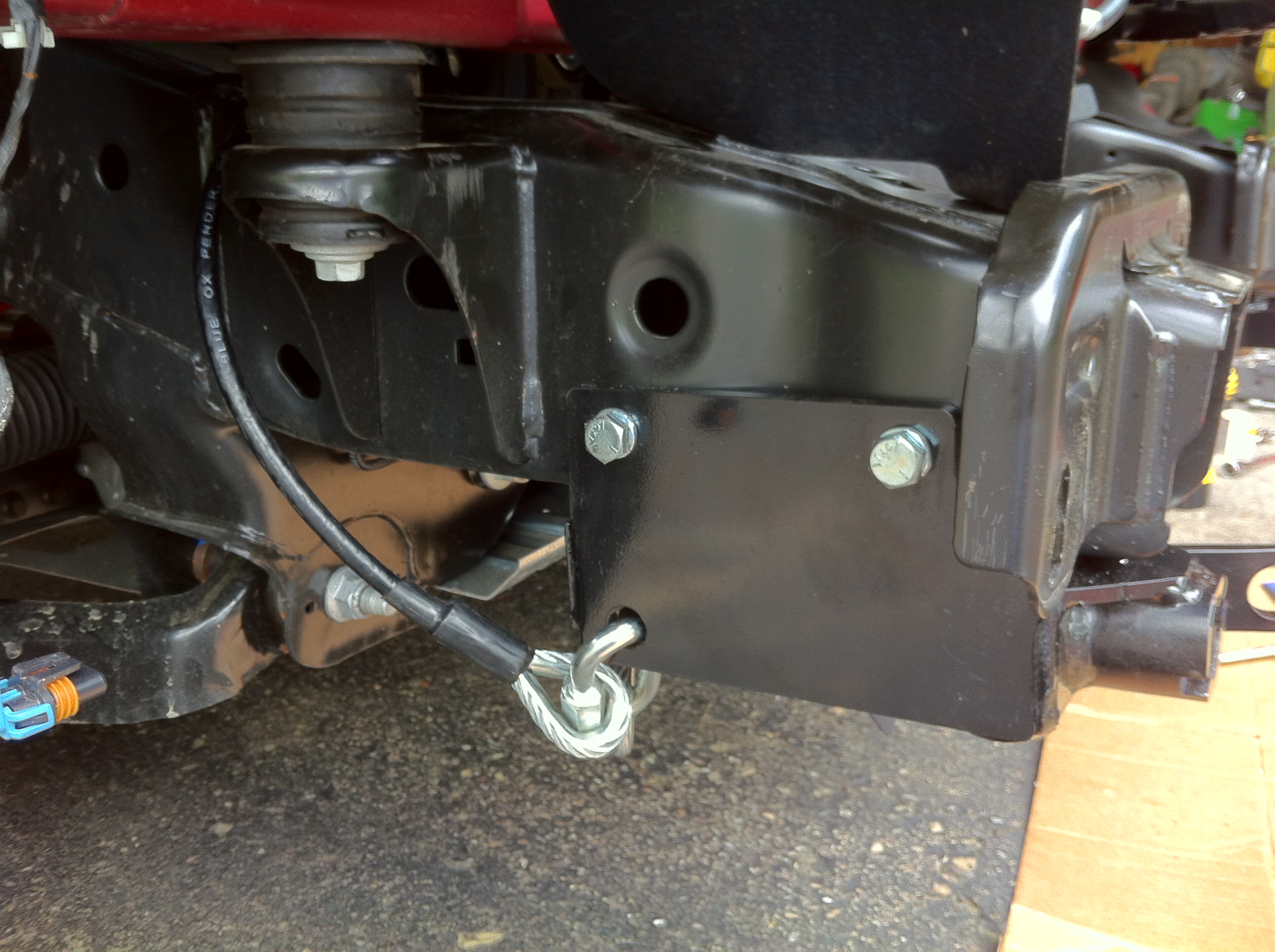
Next up is installing the permanent safety cables. The Blue Ox installation instructions show it looping over the front crossmember as one possibility, but states that options may prevent using this location. I had parts in the way of looping the cable around the crossmember, and there were hard tubing lines right where the cables would be contacting the frame. I didn't like the look of that, or the idea of the cables being so near the moving front suspension parts, so I looped the cables over the top of the frame and behind the front body mount. The quick link goes through both end loops of the cable, and through the hole in mounting bracket.
Both brackets in place:
The fussiest part of the base plate installation was re-installing the bumper. When working alone, it's tricky to get the bumper in place, hold it in the right position, and tighten the bolts. The issue is that the mounting bolt holes are oversized to allow a lot of adjustment. It took me a bit to get the bumper level and at the right height, and centered side to side. To get the final placement, I held the bumper higher than desired with one hand, and tightened the bolt with the other. Then, I loosened the bolt just enough so that I could tap the top of the bumper with my fist and nudge it down to the right height. While the rest of the installation is an easy solo project, an extra set of hands would really help during this step.
Before:
After:
Removable tab in place:
The Blue Ox BX2606 base plate is applicable to many late-model F-150s. The brackets mount in place of the front tow hooks. While the instructions state that it may require slight trimming to the front fascia, no trimming at all was required on my 2013 FX4. The brackets include removable twist-lock tabs for an unobtrusive look when not towing.
I was a bit concerned whether this base plate would fit my '13 FX4. The Blue Ox site says that it's for the XL, STX, XLT, and Harley Davidson models without EcoBoost. They don't have a specific listing for the FX4. Furthermore, one site (etrailer.com) had a note in the description that it would not fit an FX4. (I wrote to them asking about it, and they replied that they did not know why the comment was there. I now see that they have removed the comment, and it now says it's for all '11 to '13 models except EcoBoost, King Ranch, and Raptor. Had the listing said that a month ago, I wouldn't have been concerned.) I did end up writing to Blue Ox, and they assured me that the BX2606 base plate is the right one for my truck.
The base plate installation is rather straightforward, following the Blue Ox instructions. I did make a few slight deviations, which I'll detail below.
Installation starts by removing the bumper. Besides the list of tools described in the installation instructions, an air ratchet is useful to really speed things up (but nothing requires the extra power of an air impact gun.) Based on a suggestion by ron1947, I removed the air dam first. A deep 15mm socket made quick work of this. This made it easier to reach the bumper mounting bolts. The instructions call for a 21mm socket for the bumper bolts, but all of my set stop at 19mm - a 13/16 socket was a bit snug, but worked well on the bumper bolts. A minor glitch is that the hood latch is mounted to the bumper, with no mention of that in the installation instructions. I first attempted to release the cable from the latch. While it looked like it should be an easy thing to do, I had no success. So I just unbolted the latch from the bumper (10mm socket.)
Here's what the truck looks like with the hood open and without the bumper:
The air dam bolts onto a pair of studs threaded into spring clip nuts. The tow bar brackets are larger than the tow hooks, and the rear bracket bolt uses the same frame hole as the air dam. So the spring clip nuts must be removed, and according to the installation instructions, the air dam is not reinstalled.
But I like the idea of having the air dam in place, so I followed a tip gleaned from a RoadMaster base plate installation guide and mounted the air dam in an alternate location. The studs have a Torx driver profile on the end. I didn't have a matching socket, so I just used a pair of locking pliers to clamp onto the Torx splines and rotate out the stud. With the stud out, the spring clip on the nut is easy to remove. After removing the spring clip nuts, I turned them 180 degrees and reinserted them in the next set of holes toward the back of the truck, and reinstalled the studs.
This is the factory location of the air dam mounting studs: (passenger side, front of vehicle to the right)
And this is where I relocated them: (passenger side, front of vehicle to the right)
Removing the tow hooks and bolting the base plate brackets in place was very straightforward, and is covered very well by the installation instructions. It involves drilling a couple holes, which the instructions indicate should be 17/32" diameter. I used a 1/2" bit (16/32") and had no issues fitting the bolts through the holes.
Next up is installing the permanent safety cables. The Blue Ox installation instructions show it looping over the front crossmember as one possibility, but states that options may prevent using this location. I had parts in the way of looping the cable around the crossmember, and there were hard tubing lines right where the cables would be contacting the frame. I didn't like the look of that, or the idea of the cables being so near the moving front suspension parts, so I looped the cables over the top of the frame and behind the front body mount. The quick link goes through both end loops of the cable, and through the hole in mounting bracket.
Both brackets in place:

The fussiest part of the base plate installation was re-installing the bumper. When working alone, it's tricky to get the bumper in place, hold it in the right position, and tighten the bolts. The issue is that the mounting bolt holes are oversized to allow a lot of adjustment. It took me a bit to get the bumper level and at the right height, and centered side to side. To get the final placement, I held the bumper higher than desired with one hand, and tightened the bolt with the other. Then, I loosened the bolt just enough so that I could tap the top of the bumper with my fist and nudge it down to the right height. While the rest of the installation is an easy solo project, an extra set of hands would really help during this step.
Before:
After:
Removable tab in place:
Last edited by ShapeShifter; 08-21-2013 at 05:25 PM. Reason: Fixed image links and formatting
08-18-2013, 07:03 PM
#3
Senior Member
Thread Starter
Phase 2: Modify Roadmaster Tow Bar
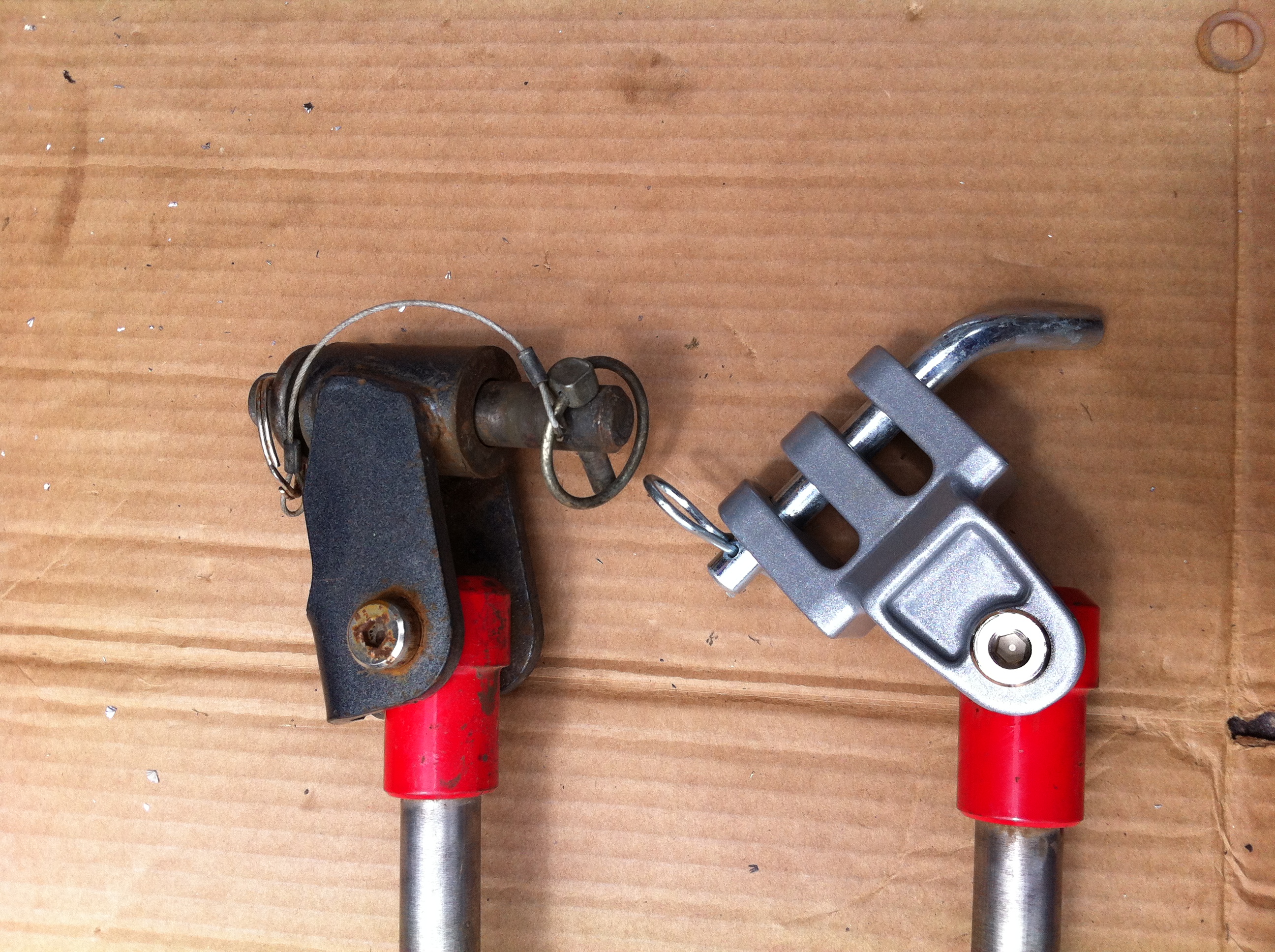
I used a RoadMaster base plate on my previous truck, and a Roadmaster Blackhawk 2 tow bar. The tow bar is still in good shape, so there is no need to replace it. However, the base plate/tow bar attachment method is very different between the Blue Ox and Roadmaster products. Fortunately, Roadmaster offers the 031 adapter kit, which mounts to the end of a Roadmaster tow bar and allows connection to a Blue Ox base plate.
Installation is very simple: At the end of the arm, remove the bolt holding on the Roadmaster style fitting, and bolt on the Blue Ox style fitting. That's it.
Here are the ends of the tow bar arms, with one side already switched out:
Last edited by ShapeShifter; 08-21-2013 at 05:26 PM.
08-18-2013, 07:06 PM
#4
Senior Member
Thread Starter
Phase 3: Install Hopkins 56000 Tail Light Wiring Kit
There are three ways to handle the tail lights of a toad:
For this install, I found the Hoppy 5600 Towed Vehicle Wiring Kit, by Hopkins. This is billed as a plug-and-play wiring solution that requires no cutting and splicing. It consists of a pre-wired harness with the required blocking diodes, and a set of connectors that match the tail light sockets.
The basic idea is that you unplug the truck's wiring from the tail light socket, plug it into one socket of the wiring kit, and plug another wiring kit socket into the tail light. No cutting or splicing required, a simple and easily reversible plug and play solution. My first step was to prepare the wiring by adding split loom tubing:
Following the installation instructions, I started by using 3M grey automotive double stick foam tape to mount the diode block behind the driver's side tail light:
The wiring going through the top hole is the factory plug that drives the top light. Next to that connector is the factory plug for the lower light which is plugged into the driver side input socket of the wiring kit. Below and to the left of that is the wiring kit plug that now connects to the lower tail light. Behind it all is the diode/junction block fastened out of the way. The back up light bulb is hanging at the bottom.
I then ran the wire to the passenger side tail light, following the existing factory wiring. There is a wiring chase formed into the body sheet metal, and I tried to run the wires through there, but the connectors were too large. So I ran the wires adjacent to this channel, and quickly discovered the wire is too short - it barely made it past the spare tire.
So I took everything out, mounted the diode block under the bed, ran the driver side wires up to the driver side tail light, and ran the passenger side wires. But they were still too short - they only reached the corner of the bed, but was not long enough to run up to the tail light itself.
After taking everything out yet again, I spliced another three feet of wire into the passenger side harness using weather resistant heat shrink crimped butt splices. I varied the position of the cuts so that the butt splices were staggered, helping prevent a big bulge in the harness:
After adding more split loom tubing, I re-installed the diode block in the original position behind the driver's side tail light, and successfully ran the harness to the passenger side. I then ran the input wires inside the driver's side frame to the front of the truck, and out of a hole in the side of the frame below the radiator and behind the bumper:
I just tied it off for now, until the final wiring connections coming up in the last phase. The wiring kit includes a flat-four connector. I wasn't planning on using it, so I cut it off right at the beginning of the process, to make running the wire easier.
There are three ways to handle the tail lights of a toad:
- Use blocking diodes to allow the motorhome to operate the truck's lights.
- Install additional light bulbs in the truck's tail lights
- Use magnetic or strap-on tow lights.
For this install, I found the Hoppy 5600 Towed Vehicle Wiring Kit, by Hopkins. This is billed as a plug-and-play wiring solution that requires no cutting and splicing. It consists of a pre-wired harness with the required blocking diodes, and a set of connectors that match the tail light sockets.

The basic idea is that you unplug the truck's wiring from the tail light socket, plug it into one socket of the wiring kit, and plug another wiring kit socket into the tail light. No cutting or splicing required, a simple and easily reversible plug and play solution. My first step was to prepare the wiring by adding split loom tubing:
Following the installation instructions, I started by using 3M grey automotive double stick foam tape to mount the diode block behind the driver's side tail light:
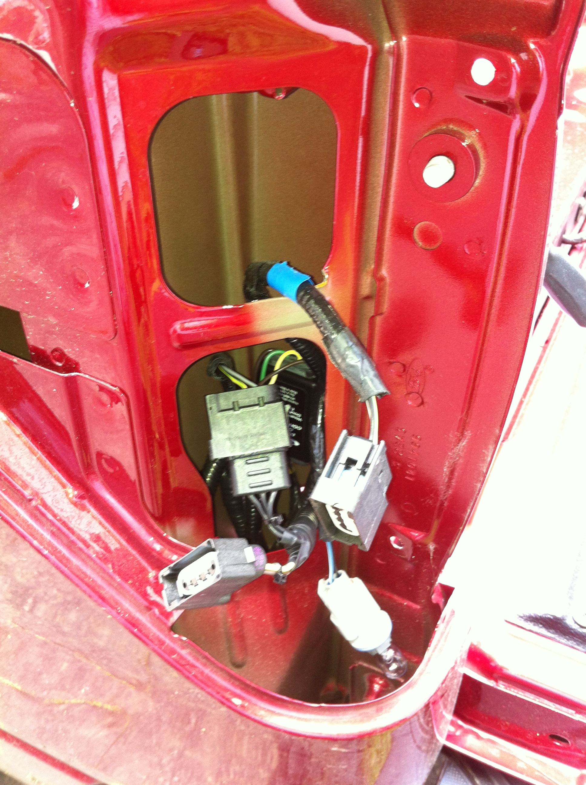
The wiring going through the top hole is the factory plug that drives the top light. Next to that connector is the factory plug for the lower light which is plugged into the driver side input socket of the wiring kit. Below and to the left of that is the wiring kit plug that now connects to the lower tail light. Behind it all is the diode/junction block fastened out of the way. The back up light bulb is hanging at the bottom.
I then ran the wire to the passenger side tail light, following the existing factory wiring. There is a wiring chase formed into the body sheet metal, and I tried to run the wires through there, but the connectors were too large. So I ran the wires adjacent to this channel, and quickly discovered the wire is too short - it barely made it past the spare tire.
So I took everything out, mounted the diode block under the bed, ran the driver side wires up to the driver side tail light, and ran the passenger side wires. But they were still too short - they only reached the corner of the bed, but was not long enough to run up to the tail light itself.
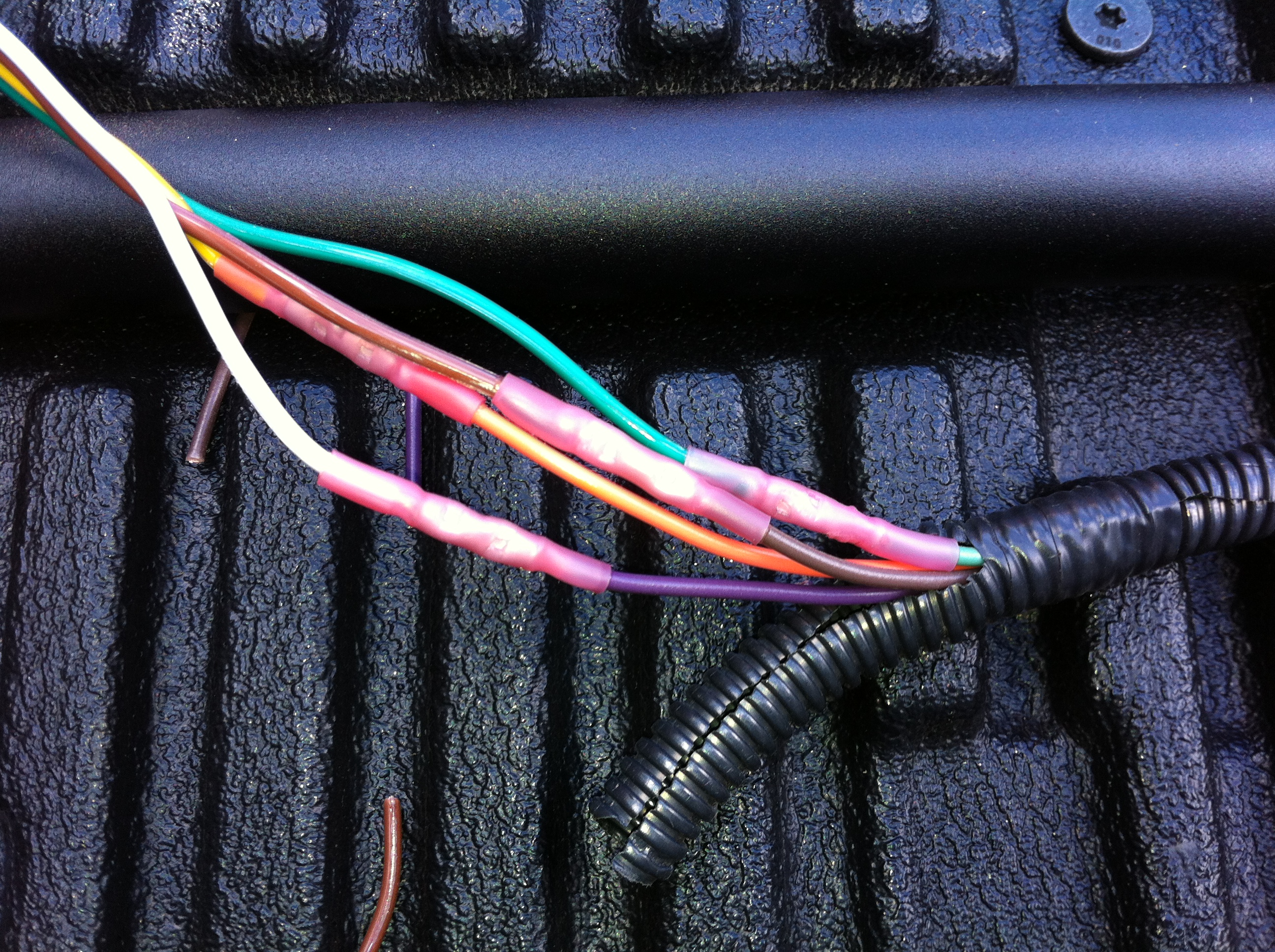
After taking everything out yet again, I spliced another three feet of wire into the passenger side harness using weather resistant heat shrink crimped butt splices. I varied the position of the cuts so that the butt splices were staggered, helping prevent a big bulge in the harness:
After adding more split loom tubing, I re-installed the diode block in the original position behind the driver's side tail light, and successfully ran the harness to the passenger side. I then ran the input wires inside the driver's side frame to the front of the truck, and out of a hole in the side of the frame below the radiator and behind the bumper:
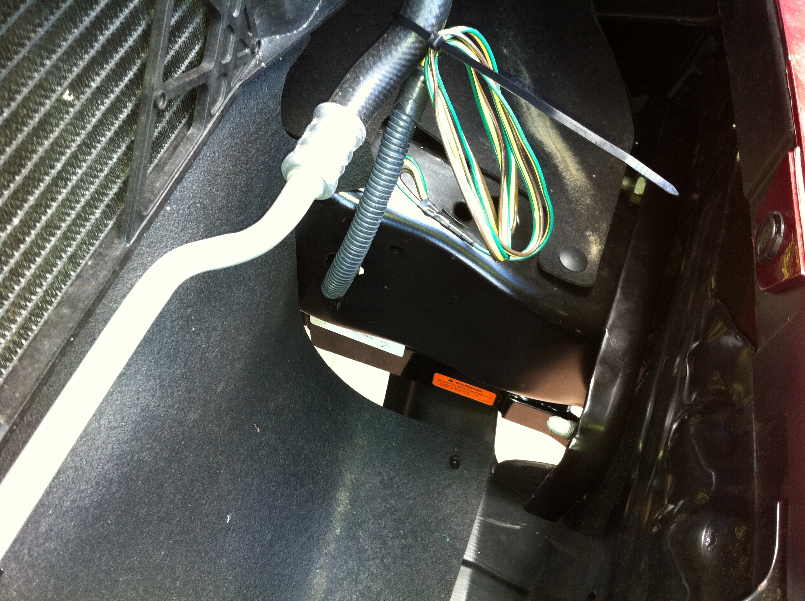
I just tied it off for now, until the final wiring connections coming up in the last phase. The wiring kit includes a flat-four connector. I wasn't planning on using it, so I cut it off right at the beginning of the process, to make running the wire easier.
Last edited by ShapeShifter; 08-21-2013 at 05:27 PM. Reason: Fix image links
08-18-2013, 07:08 PM
#5
Senior Member
Thread Starter
Phase 4: Install US Gear Unified Tow Brake
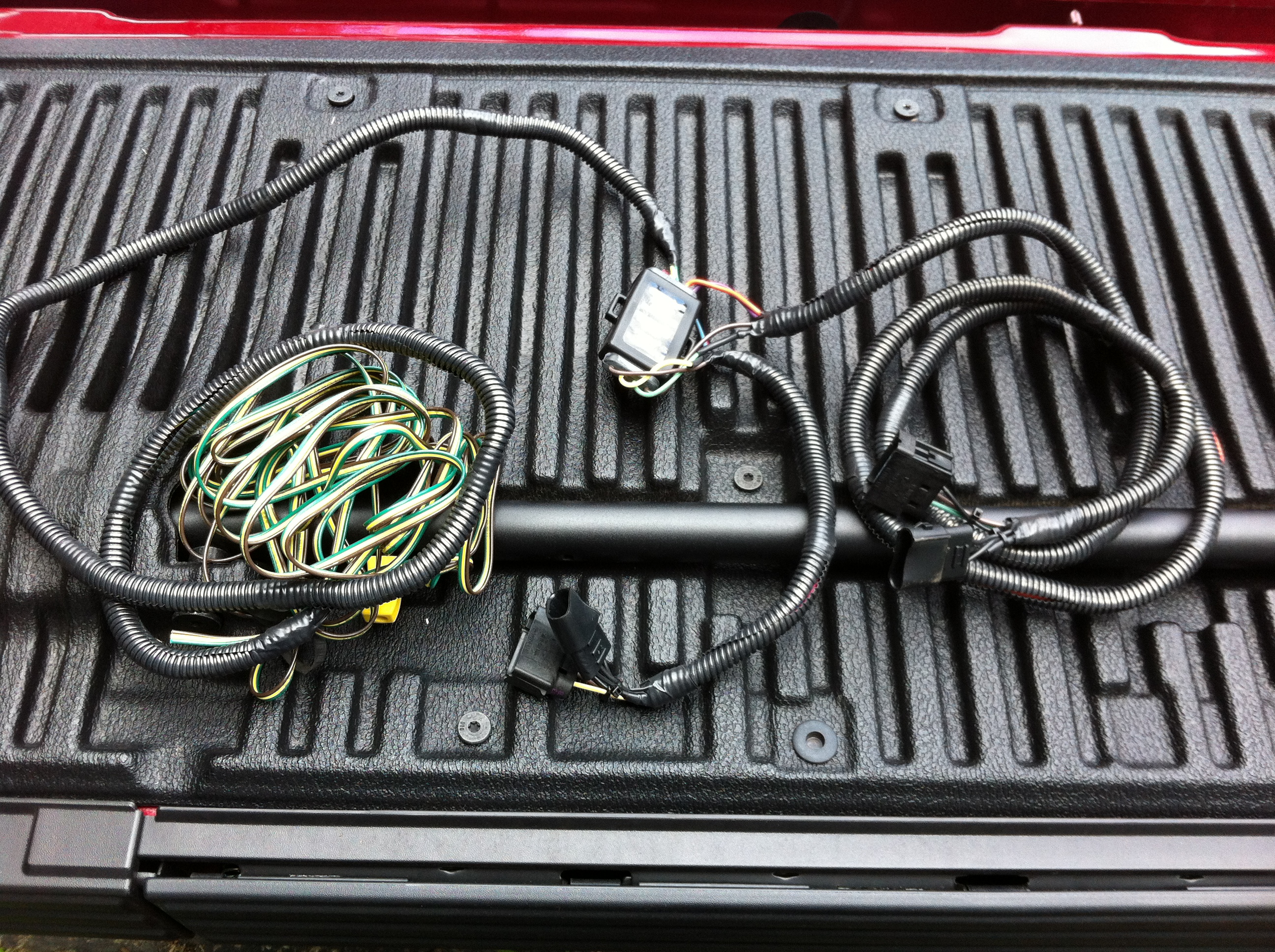
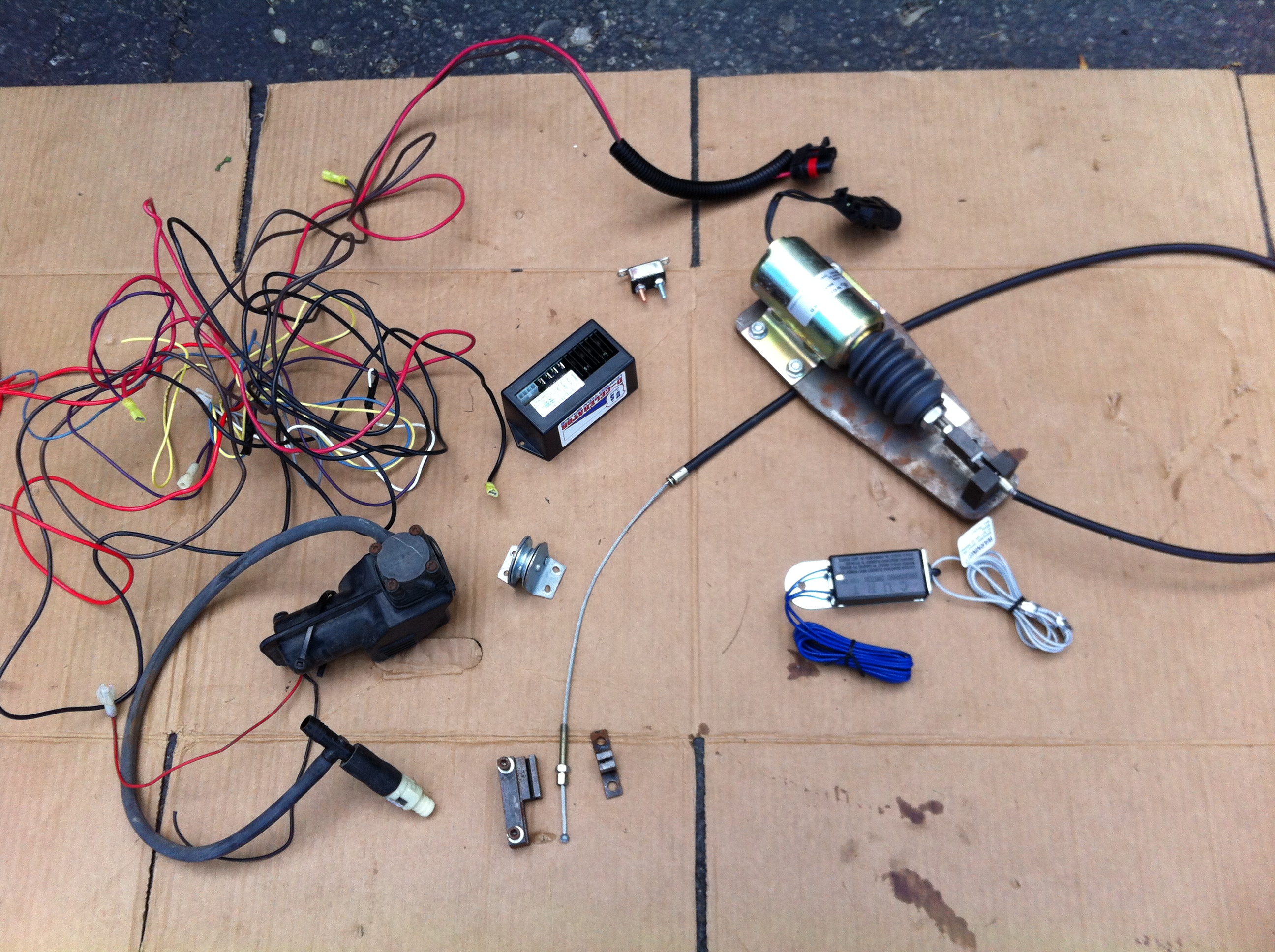
I pulled my US Gear Unified Tow Brake from my old truck, and reinstalled it in my F-150. The braking system includes an electric solenoid that uses a cable to pull on the truck's brake pedal. The system uses an electric vacuum pump to keep the truck's power brake booster charged. Because it draws electrical power to run the servo solenoid and vacuum pump, the system uses a toad battery charge line from the motorhome to the toad to keep the toad's battery charged. This line includes a 40 Amp self resetting circuit breaker on the toad end, which wasn't worth the effort of removing from the old truck, it was cheap enough to replace at an auto parts store. Also, the break-away switch was in pretty rough shape, so I left it in place and bought a new one (it's a standard trailer brake break-away switch.) While not a pretty sight after the de-installation from the old truck, the system consists of these parts:
Clockwise from top center: Black control module, silver circuit breaker, electric actuator solenoid with flexible cable, break-away switch, brake pedal clamp, vacuum pump with check valve, wiring harness, and brake cable pulley (in the center.)
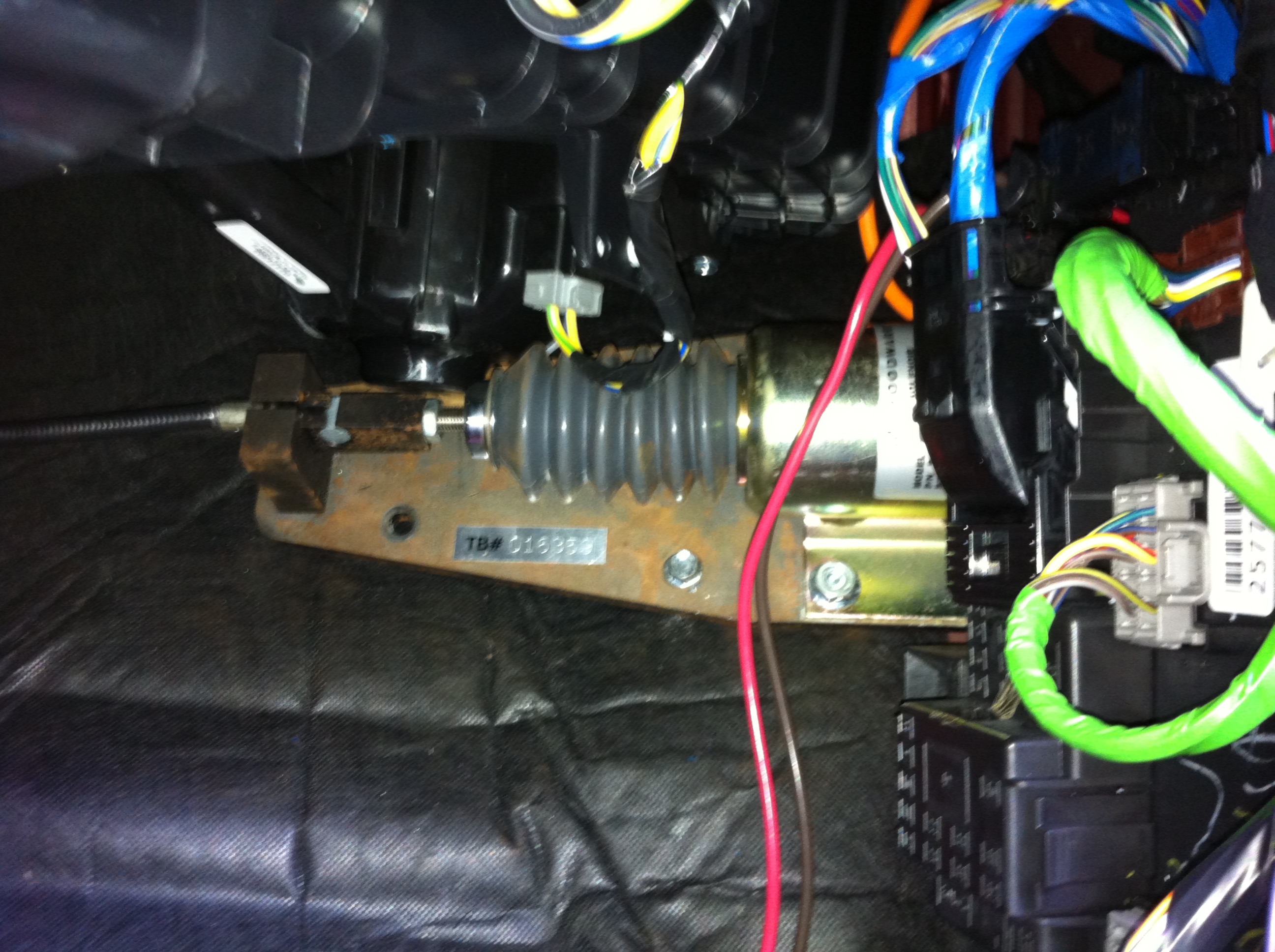
The installation instructions (video)are quite involved and detailed, and I won't repeat them here. But I will show where I placed the various components. I mounted the solenoid behind the carpeting, up high and far to the right of the passenger toe kick space:
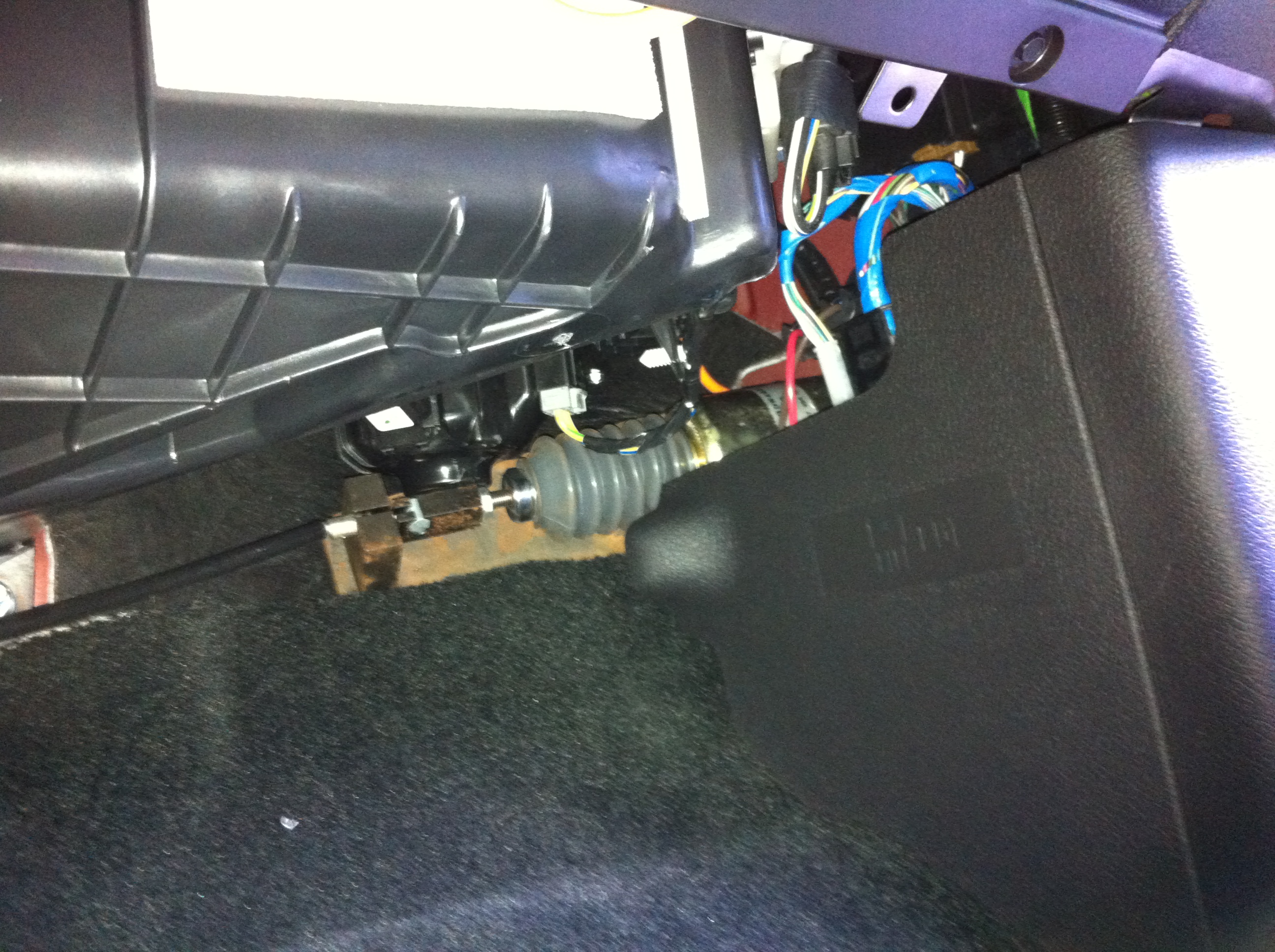
With the carpeting in place, and looking up from the floor, most of the solenoid is still visible:
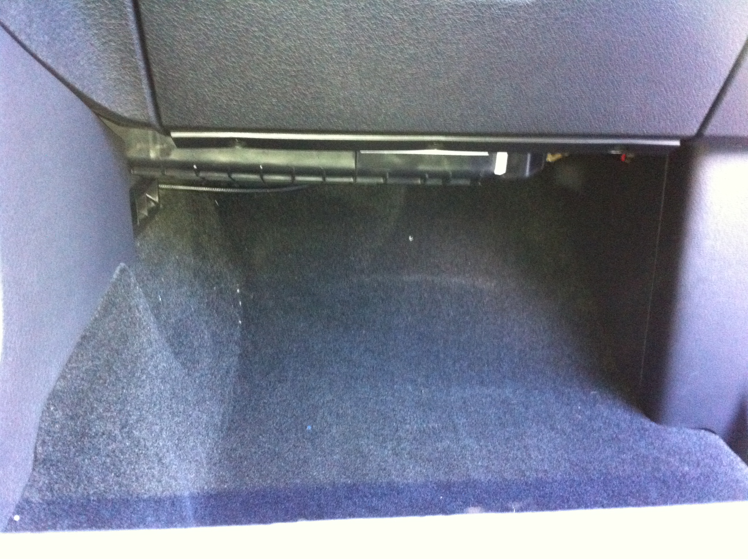
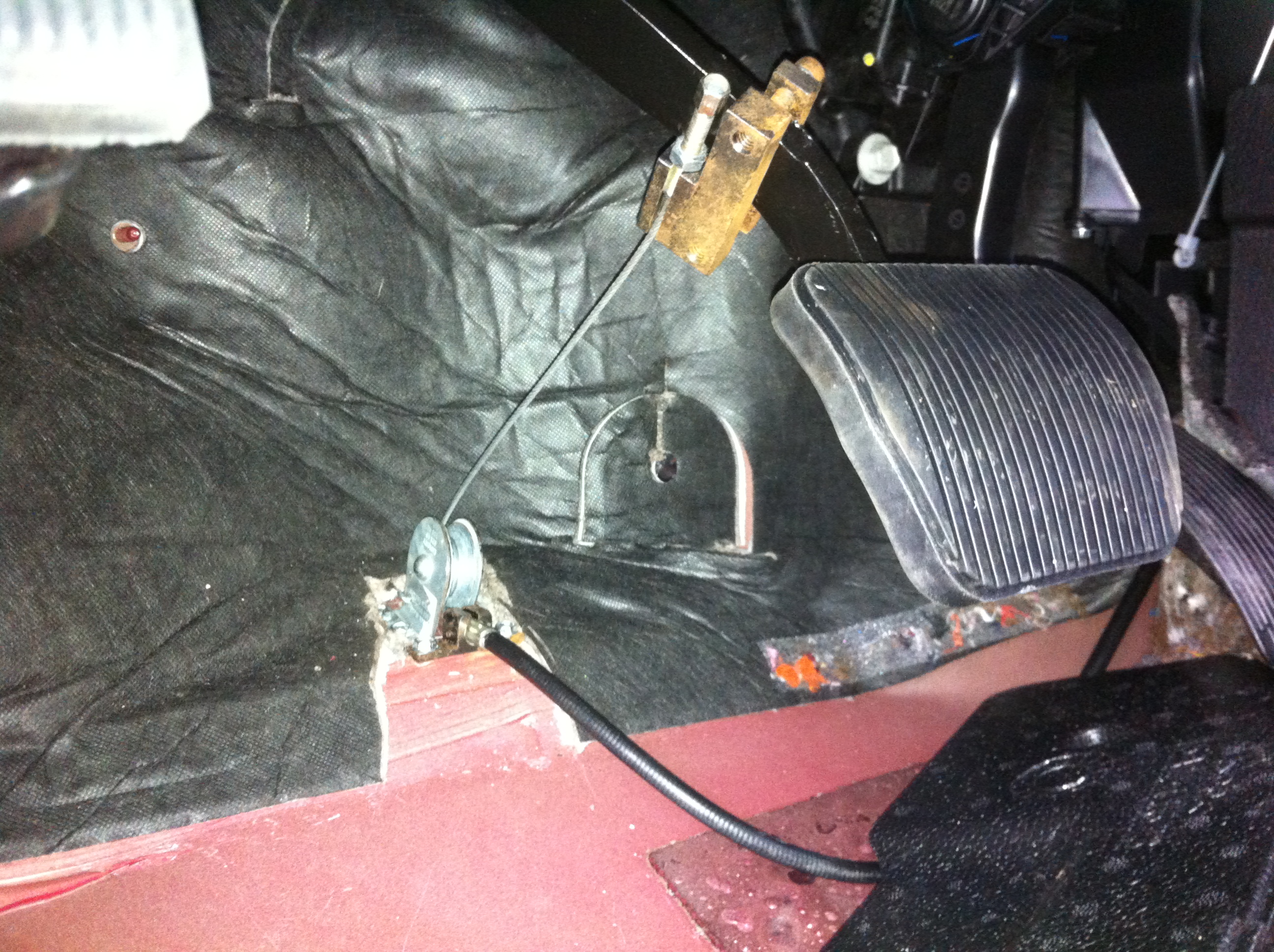
But when looking at it from a more normal sitting position, or while standing outside the truck, it's not visible at all. From a low angle with the camera down on the edge of the seat, all you can see is the cable running behind the console:
The cable pulley is mounted on the driver side firewall. After pulling back the carpet and trimming the padding, the installed pulley and cable bracket looks like this:
In this picture, the brake pedal clamp bracket is a little crooked, I fixed that since taking the picture. The bracket also has a light coating of surface rust that the camera flash really seems to have highlighted - it doesn't look that bad in person, but I guess I'll have to give that a little touch up with black paint.
Installing the pulley and cable bracket onto the firewall was the most difficult part of the brake system installation. There isn't a lot of space to work here, and you've got to contort into some interesting positions to reach it -- those contortions were a lot easier 40 years (and 100 pounds!) ago. The brake system hardware includes a set of self-drilling self-tapping screws for installing these parts. Well, the drill part of the screws were useless against the steel used in this truck - they barely even scratched the paint. I had to get out the drill and a right angle adapter and drill pilot holes for each one.
After folding the carpet back in place, I cut a short slit in it to go around the cable. The carpet completely covers the pulley and cable, and from a normal viewing position, nothing is visible (although you can see the clamp bracket on the pedal if you crouch down wile standing outside the truck.
I mounted the control box up under the dash, using nylon zip ties to mount the box to the existing wiring. The control box taps into the cold side of the brake light circuit - I used the purple wire with the white tracer at the brake light switch.
I routed all of the wires from the control box to under the hood by following the emergency brake cable, and poking a small hole in its grommet. Under the hood, I enclosed all of the wires in split loom tubing, and ran them along the fender and to the side of the radiator, hiding it as much as possible. I mounted the vacuum pump on the fender wall against the front shock tower, and you can see the split loom running across the fender between the pump and the hood support gas strut:
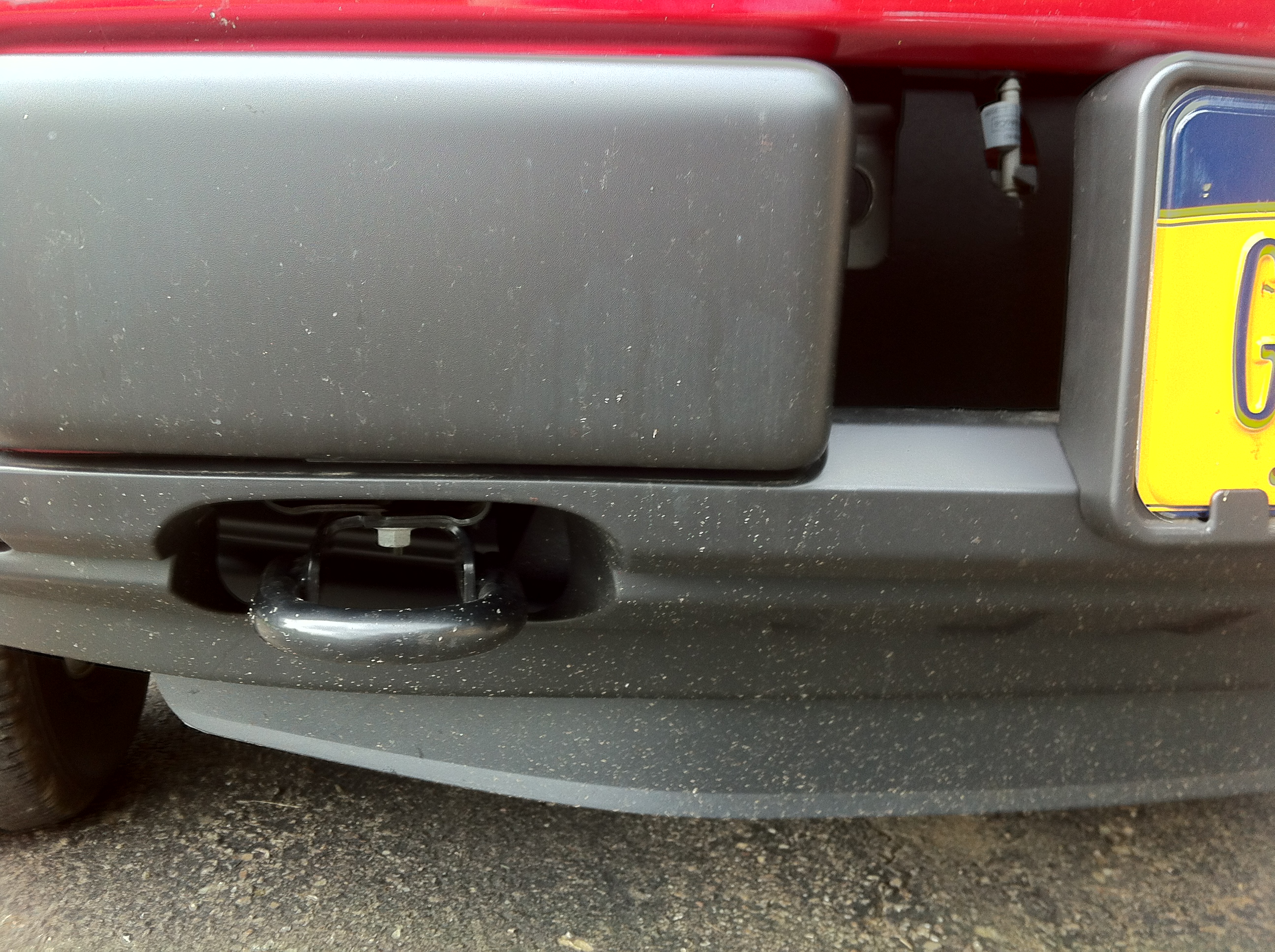
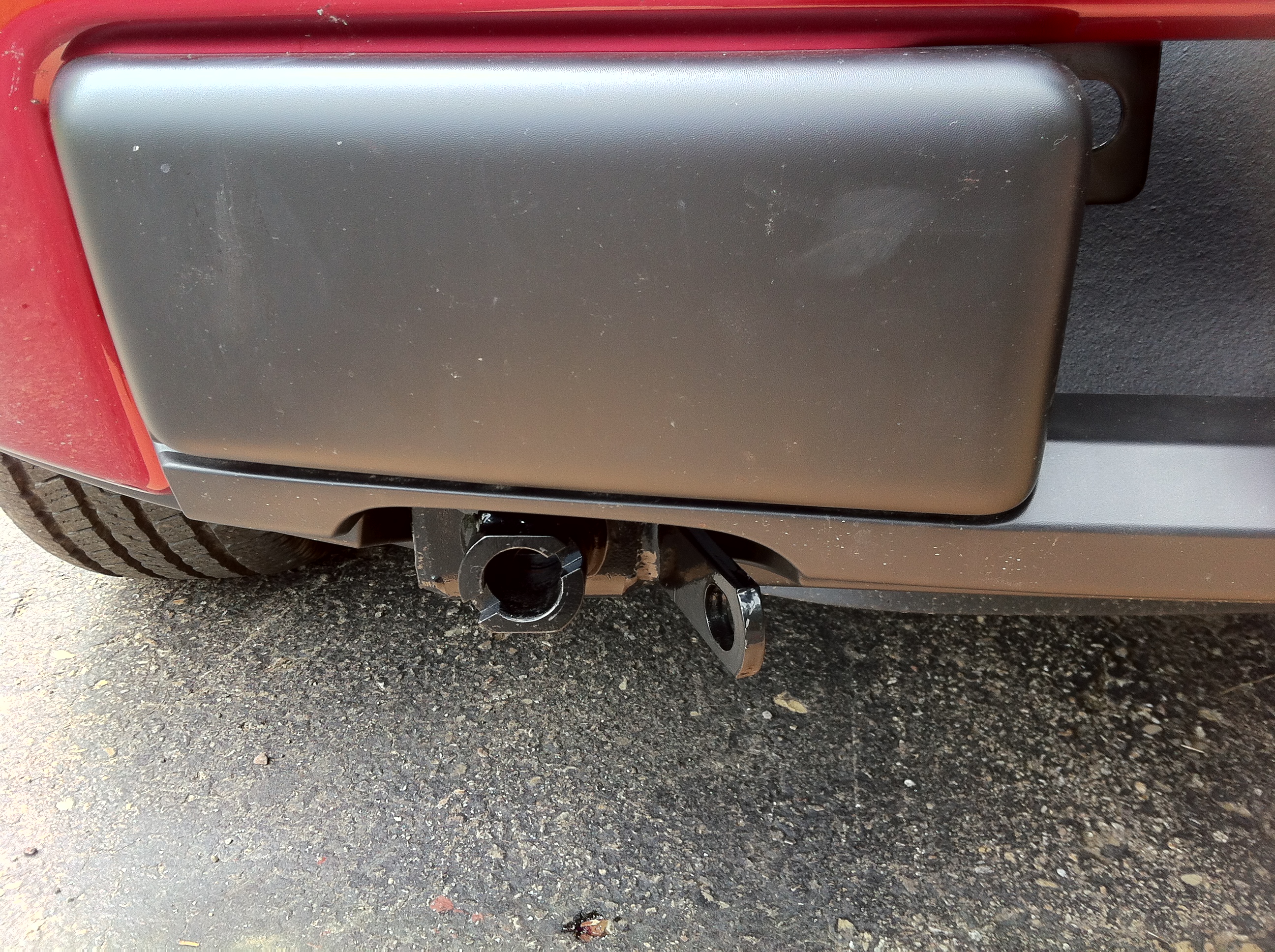
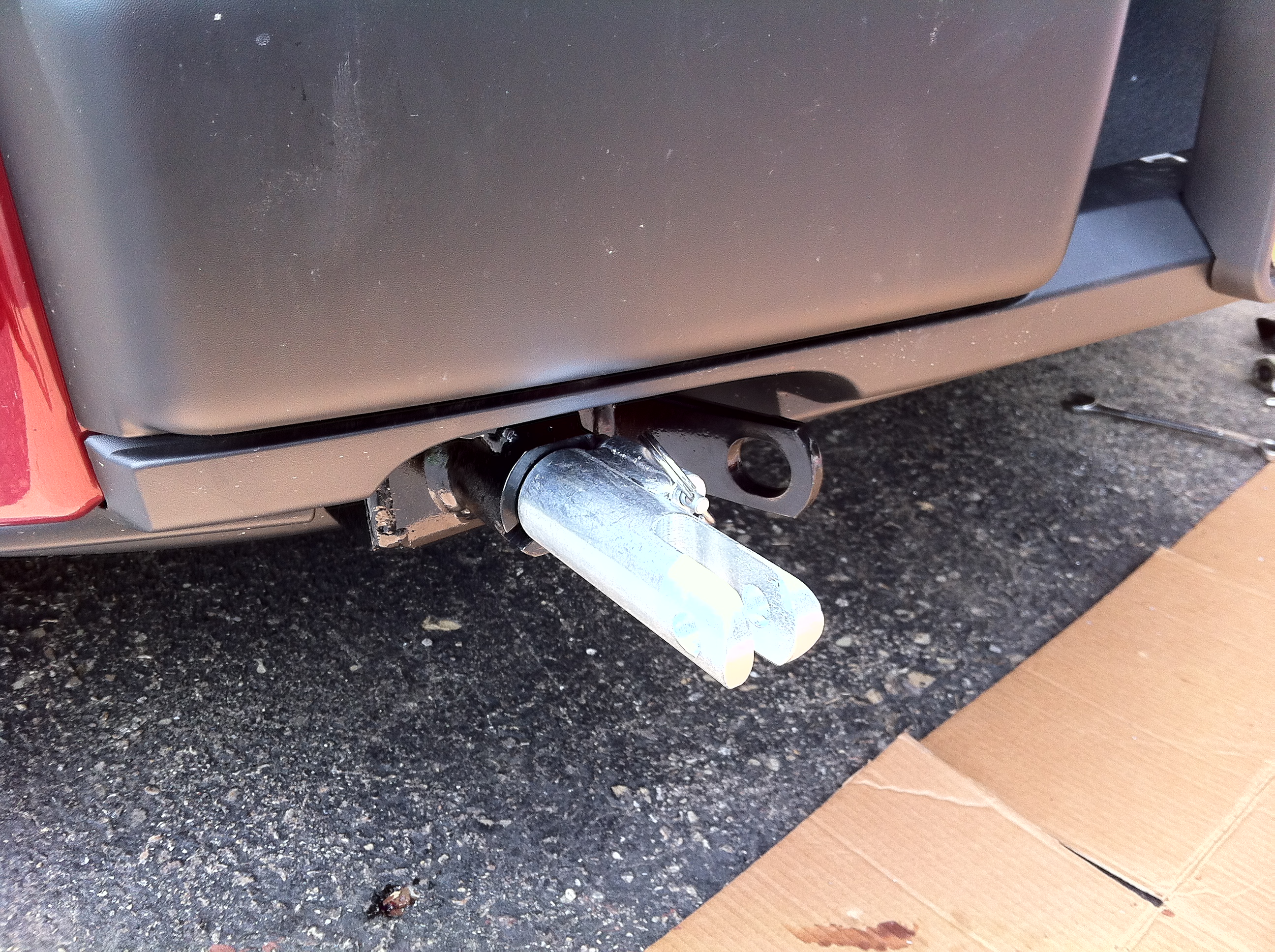
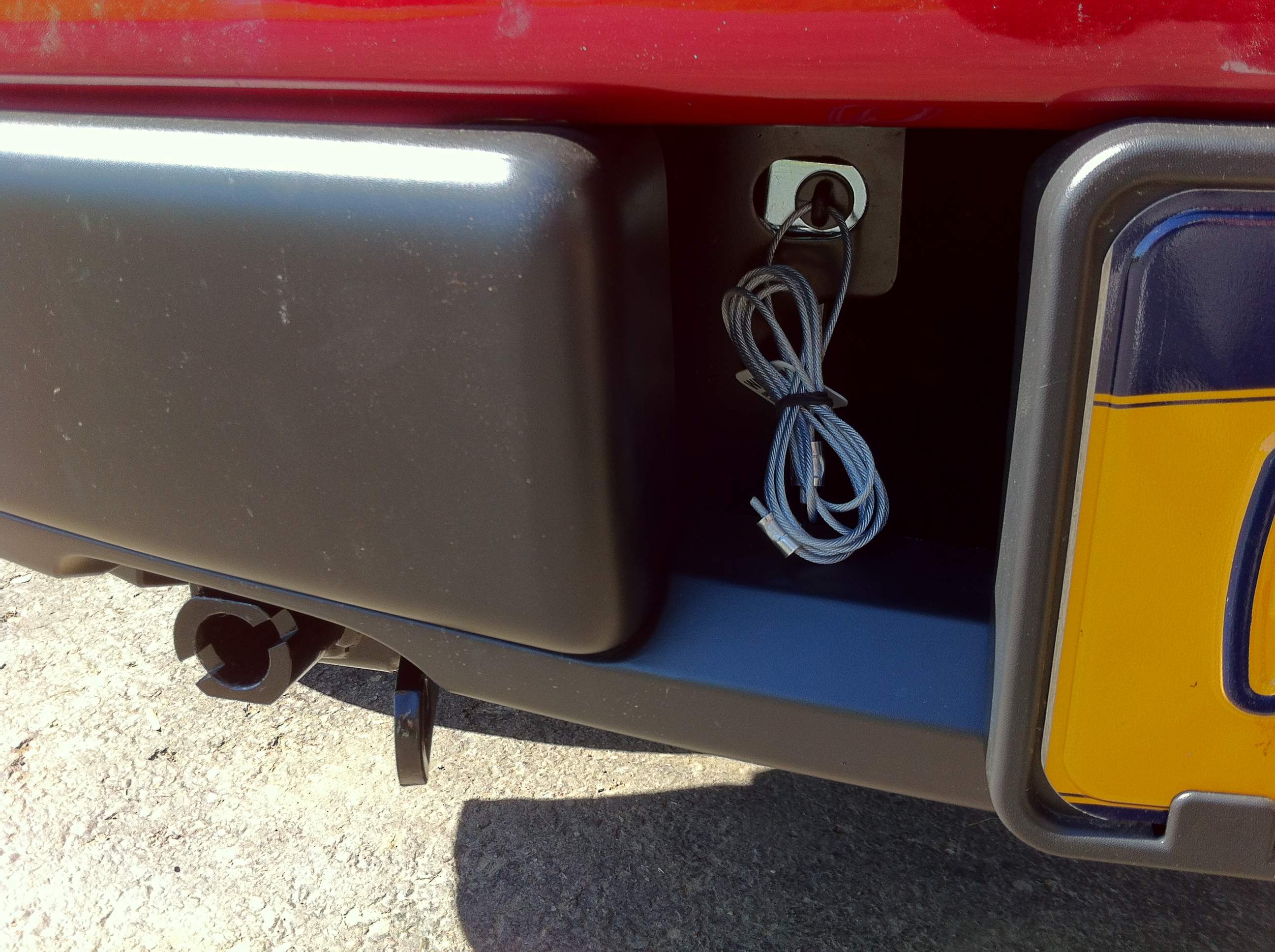
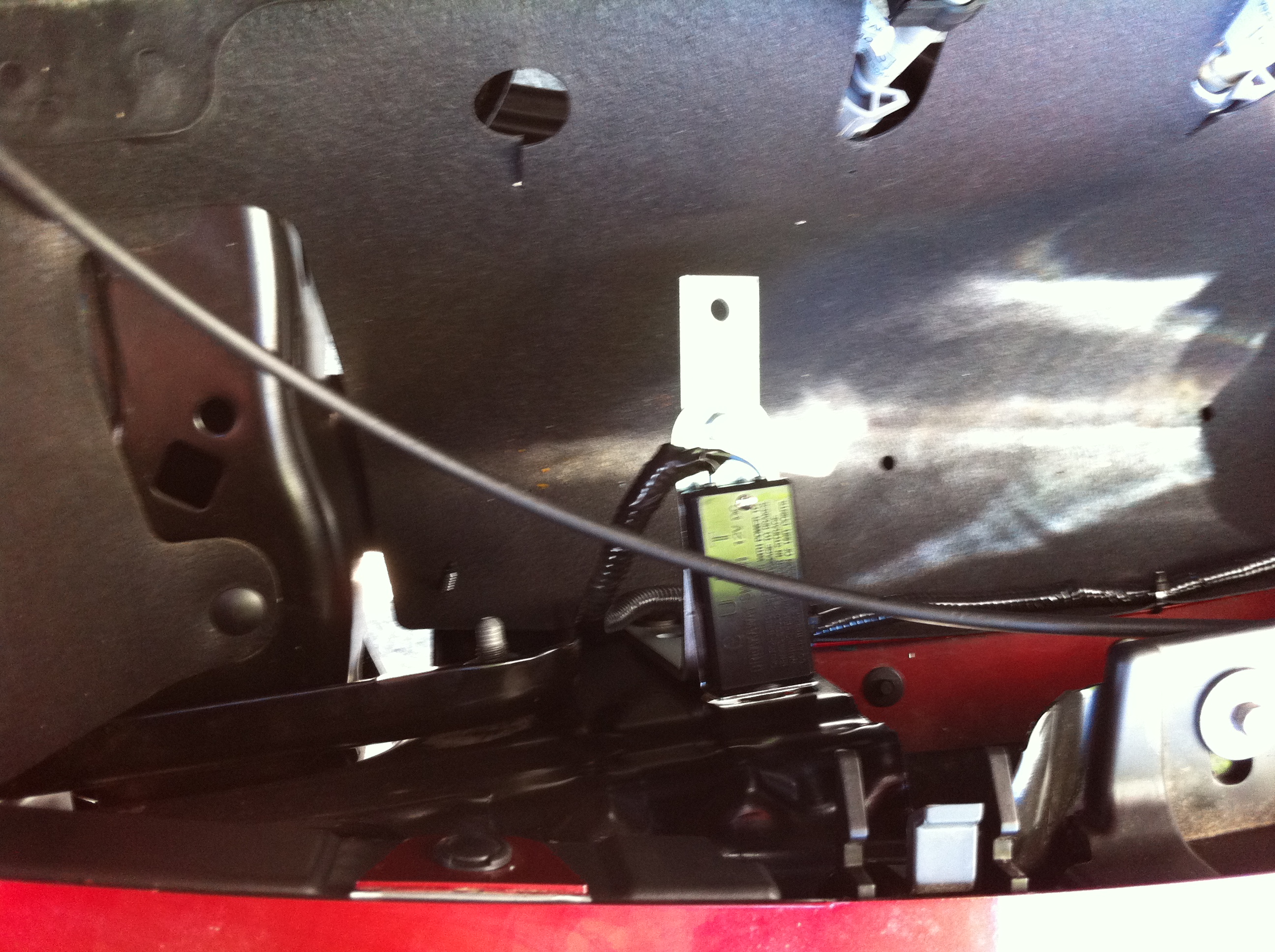
I got a thick 8" angle bracket from Lowes and drilled a couple extra holes in it. One is used to mount the bracket behind the bumper using an existing mounting bolt and nut. The break-away switch is bolted in place using the other drilled hole. This puts the break-away switch on the passenger side of the truck, peeking out of the existing hole in the bumper bracket:
I will eventually remove the fixed cable and replace it with a simple loop. Then my existing break-away cable, which has a spring clip on the end, will simply clip onto the loop. (The plunger remains in the switch all the time. If it were removed, the brake system is immediately and fully applied, and the internal contacts are prone to corrosion.)
Looking behind the bumper from above:
With all of the wires run to the front of the truck, most of the connections are made in the next phase.
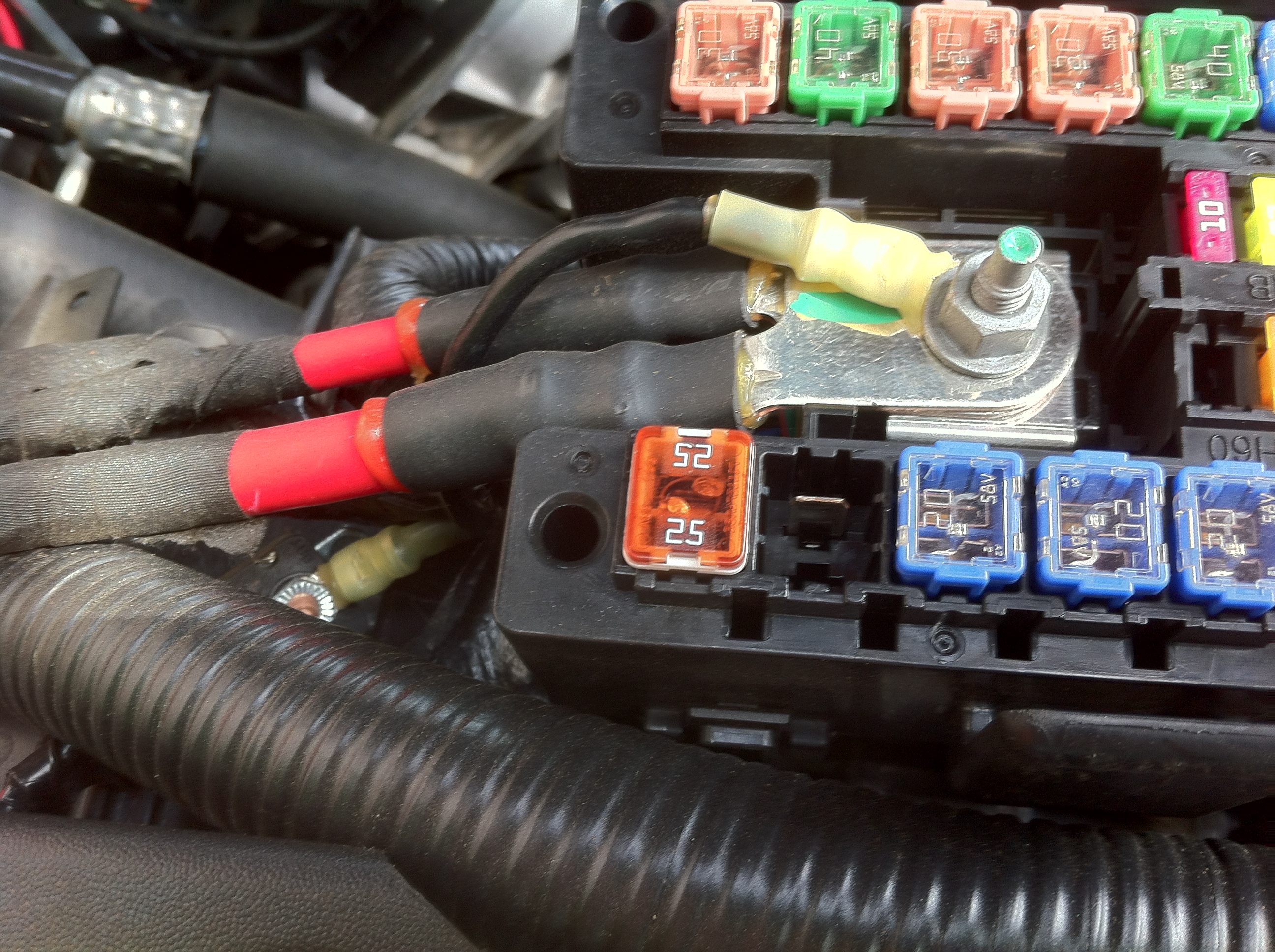
One final brake system connection is the power: I used a 40A circuit breaker, and fed it with a short wire connected to the input stud of the under-hood fuse box. The circuit breaker is simply tucked under the wiring above the radiator, and the wire runs across the top of the radiator to the rest of the system.
I pulled my US Gear Unified Tow Brake from my old truck, and reinstalled it in my F-150. The braking system includes an electric solenoid that uses a cable to pull on the truck's brake pedal. The system uses an electric vacuum pump to keep the truck's power brake booster charged. Because it draws electrical power to run the servo solenoid and vacuum pump, the system uses a toad battery charge line from the motorhome to the toad to keep the toad's battery charged. This line includes a 40 Amp self resetting circuit breaker on the toad end, which wasn't worth the effort of removing from the old truck, it was cheap enough to replace at an auto parts store. Also, the break-away switch was in pretty rough shape, so I left it in place and bought a new one (it's a standard trailer brake break-away switch.) While not a pretty sight after the de-installation from the old truck, the system consists of these parts:
Clockwise from top center: Black control module, silver circuit breaker, electric actuator solenoid with flexible cable, break-away switch, brake pedal clamp, vacuum pump with check valve, wiring harness, and brake cable pulley (in the center.)
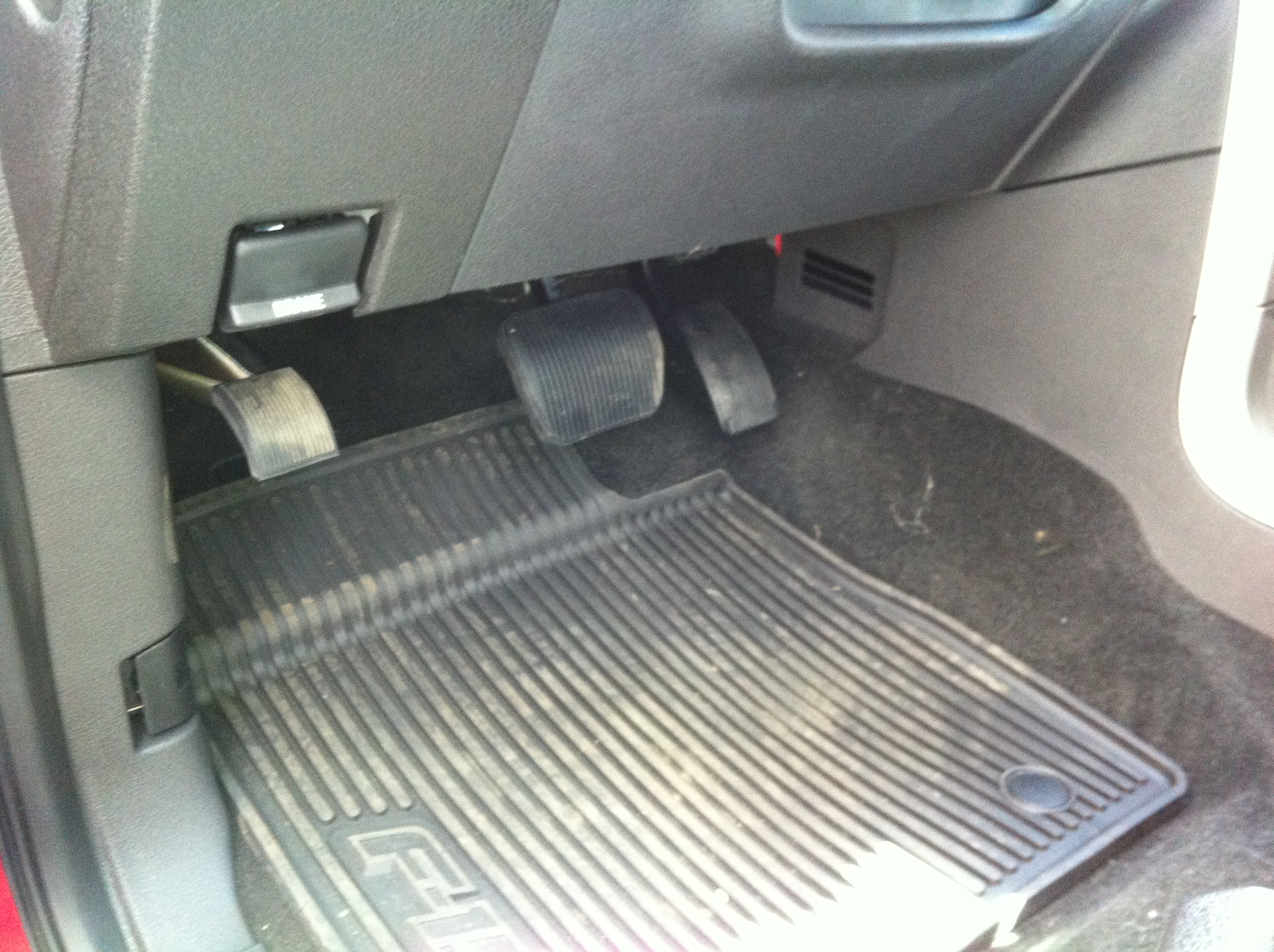
The installation instructions (video)are quite involved and detailed, and I won't repeat them here. But I will show where I placed the various components. I mounted the solenoid behind the carpeting, up high and far to the right of the passenger toe kick space:
With the carpeting in place, and looking up from the floor, most of the solenoid is still visible:
But when looking at it from a more normal sitting position, or while standing outside the truck, it's not visible at all. From a low angle with the camera down on the edge of the seat, all you can see is the cable running behind the console:
The cable pulley is mounted on the driver side firewall. After pulling back the carpet and trimming the padding, the installed pulley and cable bracket looks like this:
In this picture, the brake pedal clamp bracket is a little crooked, I fixed that since taking the picture. The bracket also has a light coating of surface rust that the camera flash really seems to have highlighted - it doesn't look that bad in person, but I guess I'll have to give that a little touch up with black paint.
Installing the pulley and cable bracket onto the firewall was the most difficult part of the brake system installation. There isn't a lot of space to work here, and you've got to contort into some interesting positions to reach it -- those contortions were a lot easier 40 years (and 100 pounds!) ago. The brake system hardware includes a set of self-drilling self-tapping screws for installing these parts. Well, the drill part of the screws were useless against the steel used in this truck - they barely even scratched the paint. I had to get out the drill and a right angle adapter and drill pilot holes for each one.
After folding the carpet back in place, I cut a short slit in it to go around the cable. The carpet completely covers the pulley and cable, and from a normal viewing position, nothing is visible (although you can see the clamp bracket on the pedal if you crouch down wile standing outside the truck.
I mounted the control box up under the dash, using nylon zip ties to mount the box to the existing wiring. The control box taps into the cold side of the brake light circuit - I used the purple wire with the white tracer at the brake light switch.
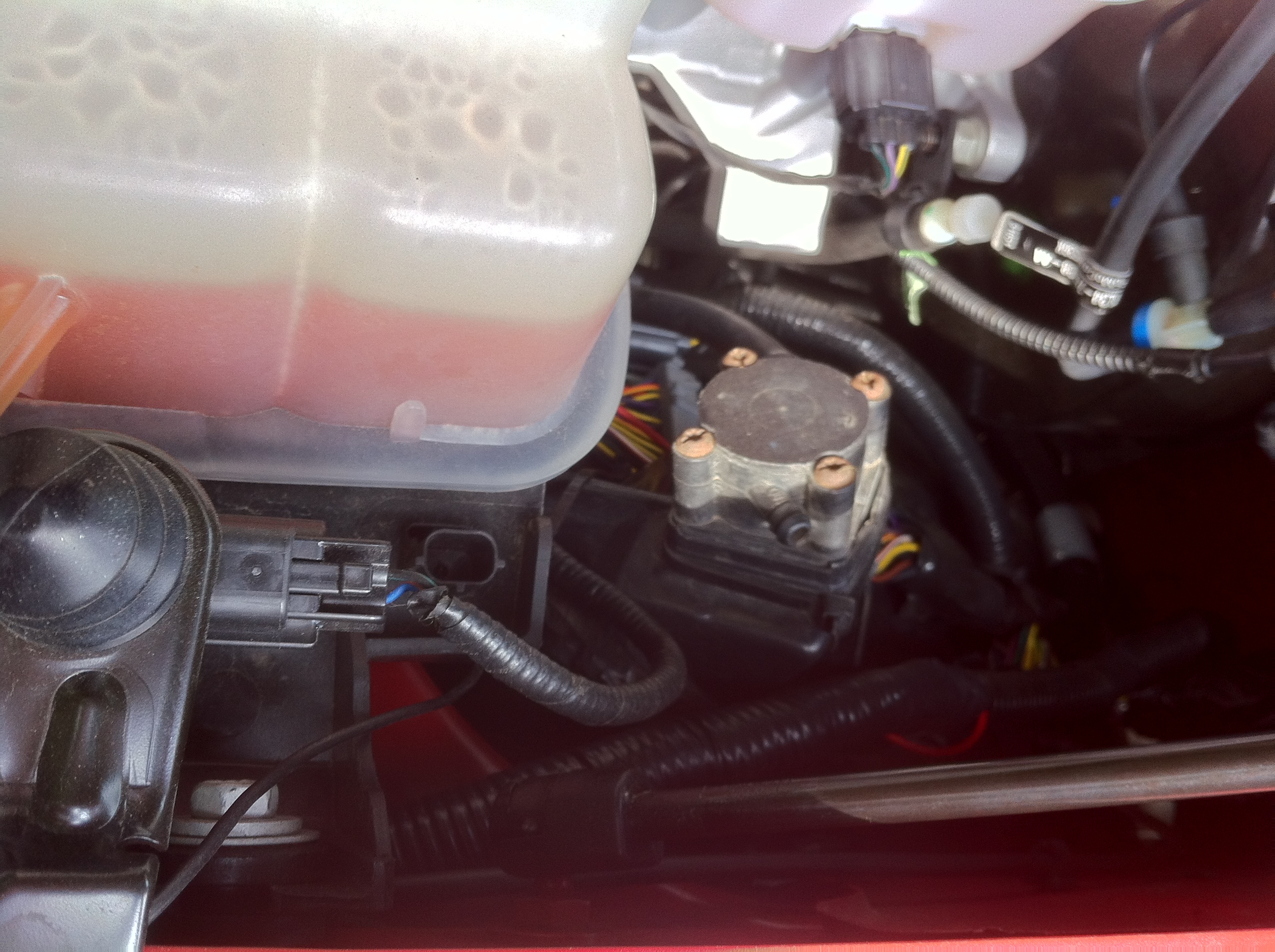
I routed all of the wires from the control box to under the hood by following the emergency brake cable, and poking a small hole in its grommet. Under the hood, I enclosed all of the wires in split loom tubing, and ran them along the fender and to the side of the radiator, hiding it as much as possible. I mounted the vacuum pump on the fender wall against the front shock tower, and you can see the split loom running across the fender between the pump and the hood support gas strut:
I got a thick 8" angle bracket from Lowes and drilled a couple extra holes in it. One is used to mount the bracket behind the bumper using an existing mounting bolt and nut. The break-away switch is bolted in place using the other drilled hole. This puts the break-away switch on the passenger side of the truck, peeking out of the existing hole in the bumper bracket:
I will eventually remove the fixed cable and replace it with a simple loop. Then my existing break-away cable, which has a spring clip on the end, will simply clip onto the loop. (The plunger remains in the switch all the time. If it were removed, the brake system is immediately and fully applied, and the internal contacts are prone to corrosion.)
Looking behind the bumper from above:
With all of the wires run to the front of the truck, most of the connections are made in the next phase.
One final brake system connection is the power: I used a 40A circuit breaker, and fed it with a short wire connected to the input stud of the under-hood fuse box. The circuit breaker is simply tucked under the wiring above the radiator, and the wire runs across the top of the radiator to the rest of the system.
Last edited by ShapeShifter; 08-21-2013 at 05:27 PM. Reason: Fix image links
08-18-2013, 07:10 PM
#6
Senior Member
Thread Starter
Phase 5: Wire it all together
I use an umbilical with a six pin round connector, to provide the electrical connections for the lighting and the braking system. The six standard pin functions work perfectly for this operation:
For the vehicle end, I used Hoppy 47155 4 Wire Flat to 6 Pole Round wiring kit by Hopkins. I thought it would make things easier since it includes the 6 pin socket, and is pre-wired with a flat-four connector for the lights, and blunt-cut wires for the remaining circuits. The plan was to simply connect the two flat-four connectors together. Unfortunately, both connectors are the same gender and won't mate. So I cut them off and spliced the wires using more heat shrink weather resistant butt connectors. Just as well, cutting off the plug from the tail light harness made it easier to snake the wires through the frame, and cutting/splicing the wires got rid off any loops of excess wires. Having the connector prewired did save some time and effort, but I could've probably saved a few dollars and eliminated a few splices if I used a standard unwired socket.
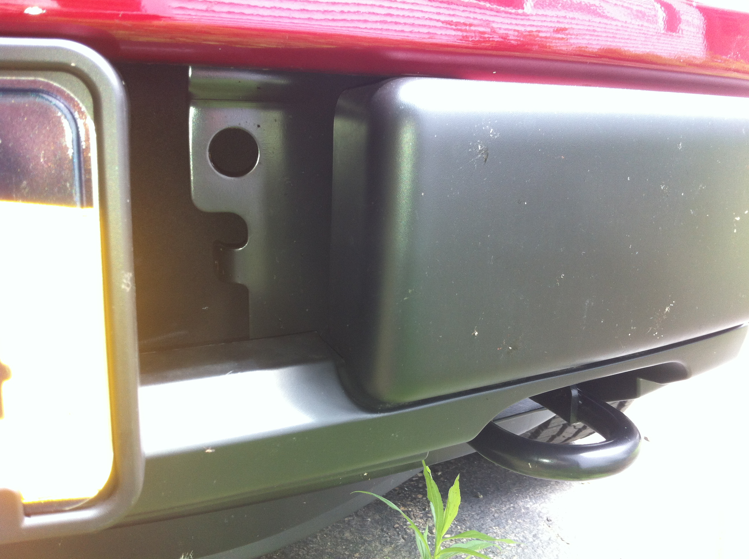
The metal mounting plate behind the driver's side of the bumper includes a large hole:
I was hoping to use that to hold the wiring connector, but the diameter of the hole is too small to pass the body of the six pin connector. Maybe you could fit a four pin socket in that hole, but I wanted the extra pins for the braking system. I was also concerned that the socket would be too high and too close to the edge of the opening to easily mate the umbilical, so I didn't drill out the hole to make it larger.
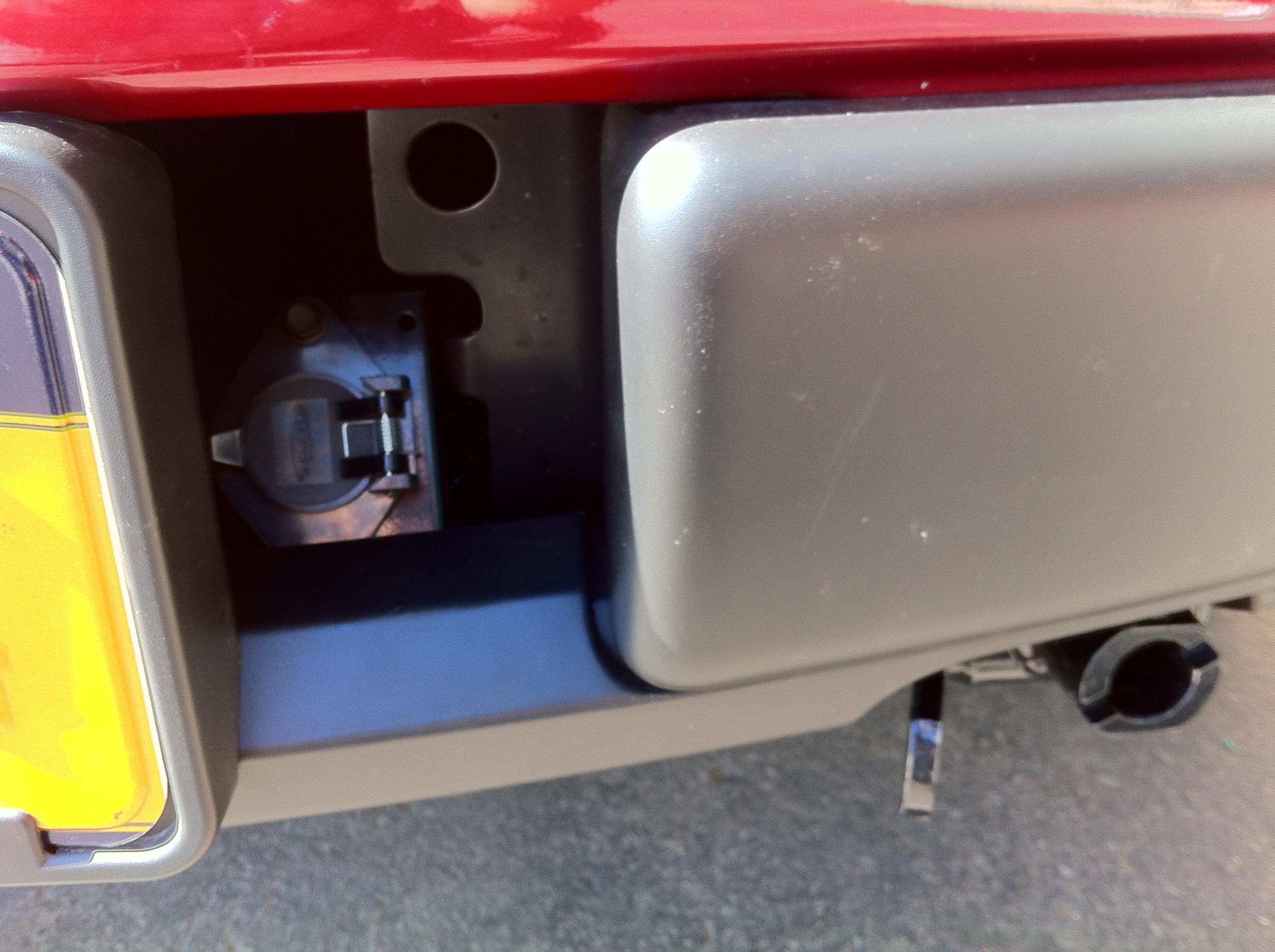
A bit lower down, that plate has a tab that bends back toward the back of the truck. This tab has a small hole, and I used that to mount the connector's mounting bracket. The connector is recessed back from the bumper making it somewhat unobtrusive, but is still easy to reach. By mounting the socket with the cover hinge to the the right, there is plenty of room to reach in and hold the cover back with your right hand, while plugging the umbilical cord in with your left hand. If you're right handed, mounting it the other way with the hinge to the left would allow you to hold the cover with your left hand, making it easier to mate the cable with your right hand. While I would've preferred this orientation, the cover would interfere with the license plate holder and not leave enough room to hold it out of the way while making the connection. But if you don't have a front license plate, and are right handed, that would be the way to go.
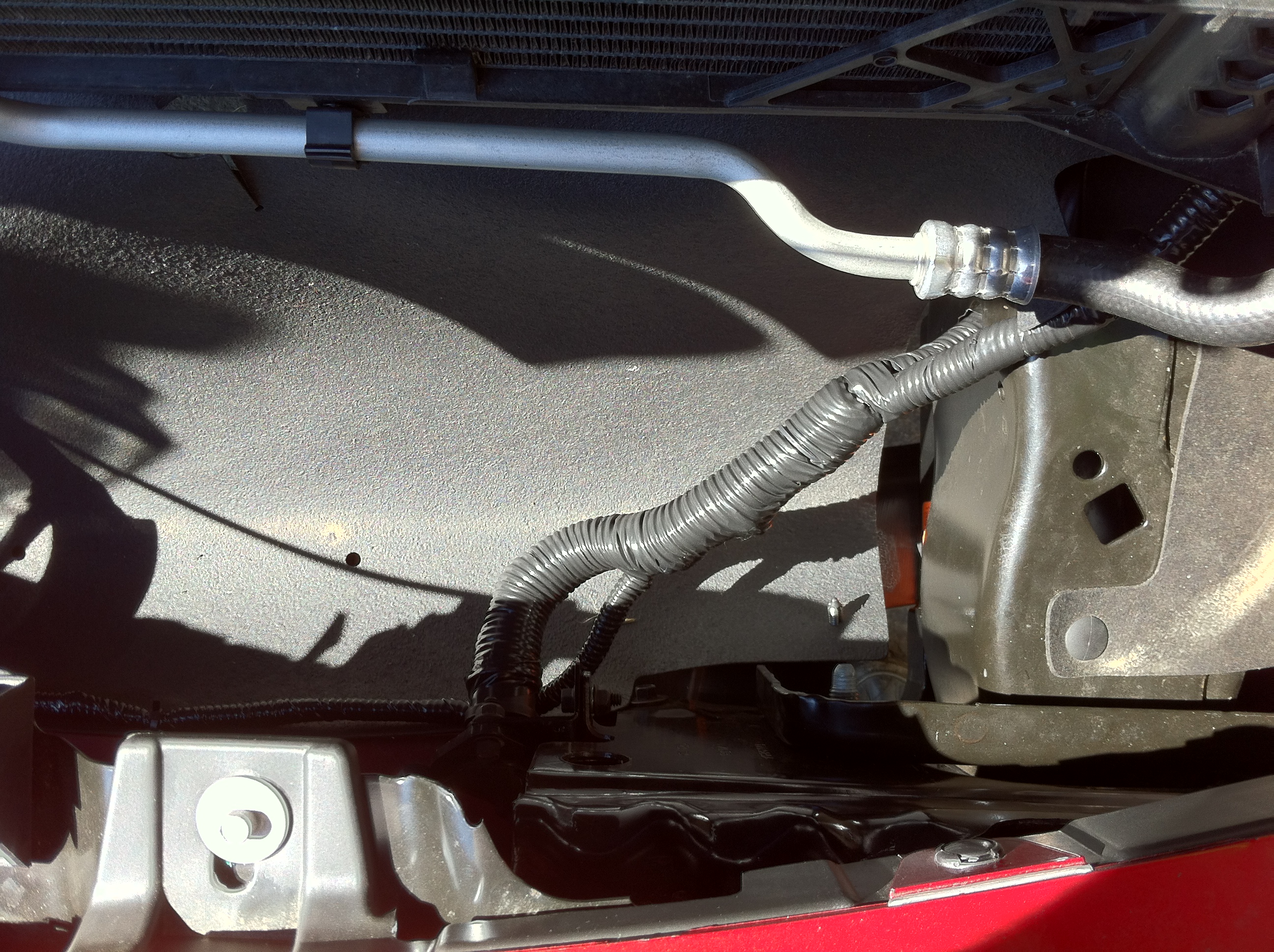
After splicing all of the wires together, I dressed them and covered them in split loom tubing. Looking looking straight down behind the bumper, the thin cable across the front (bottom of photo) comes from the break-away switch, the small cable to the back right is the lighting going into the frame, and the top cable to the right runs up along the side of the radiator to the cab and braking system. The thick bundle goes to the six pin socket:
I use an umbilical with a six pin round connector, to provide the electrical connections for the lighting and the braking system. The six standard pin functions work perfectly for this operation:
- Left turn/brake
- Right turn/brake
- Parking/running lights
- Ground
- Brake control
- Battery power
For the vehicle end, I used Hoppy 47155 4 Wire Flat to 6 Pole Round wiring kit by Hopkins. I thought it would make things easier since it includes the 6 pin socket, and is pre-wired with a flat-four connector for the lights, and blunt-cut wires for the remaining circuits. The plan was to simply connect the two flat-four connectors together. Unfortunately, both connectors are the same gender and won't mate. So I cut them off and spliced the wires using more heat shrink weather resistant butt connectors. Just as well, cutting off the plug from the tail light harness made it easier to snake the wires through the frame, and cutting/splicing the wires got rid off any loops of excess wires. Having the connector prewired did save some time and effort, but I could've probably saved a few dollars and eliminated a few splices if I used a standard unwired socket.
The metal mounting plate behind the driver's side of the bumper includes a large hole:
I was hoping to use that to hold the wiring connector, but the diameter of the hole is too small to pass the body of the six pin connector. Maybe you could fit a four pin socket in that hole, but I wanted the extra pins for the braking system. I was also concerned that the socket would be too high and too close to the edge of the opening to easily mate the umbilical, so I didn't drill out the hole to make it larger.
A bit lower down, that plate has a tab that bends back toward the back of the truck. This tab has a small hole, and I used that to mount the connector's mounting bracket. The connector is recessed back from the bumper making it somewhat unobtrusive, but is still easy to reach. By mounting the socket with the cover hinge to the the right, there is plenty of room to reach in and hold the cover back with your right hand, while plugging the umbilical cord in with your left hand. If you're right handed, mounting it the other way with the hinge to the left would allow you to hold the cover with your left hand, making it easier to mate the cable with your right hand. While I would've preferred this orientation, the cover would interfere with the license plate holder and not leave enough room to hold it out of the way while making the connection. But if you don't have a front license plate, and are right handed, that would be the way to go.
After splicing all of the wires together, I dressed them and covered them in split loom tubing. Looking looking straight down behind the bumper, the thin cable across the front (bottom of photo) comes from the break-away switch, the small cable to the back right is the lighting going into the frame, and the top cable to the right runs up along the side of the radiator to the cab and braking system. The thick bundle goes to the six pin socket:
Last edited by ShapeShifter; 08-21-2013 at 05:28 PM.
The following 2 users liked this post by ShapeShifter:
moseby (09-02-2013),
powerboatr (09-02-2013)
08-18-2013, 07:11 PM
#7
Member

What an awesome write up.
The following users liked this post:
ShapeShifter (08-24-2013)
Trending Topics
08-18-2013, 07:11 PM
#8
Senior Member
Thread Starter
Conclusion:
Installation was somewhat involved, but not overly complicated. It took me the better part of two days to do everything. The most time consuming portions were installing the brake system pulley on the fire wall (limited access and self-drilling screws that didn't drill) and running/lengthening the taillight wiring (harness was too short.) The hardest part was getting up the courage to take apart and modify a truck that was only a week old. (Modifying my last truck for towing was easier, I'd had it for 6 years at that point, and already had done many mods to it.)
But in the end, everything works, and works well. A few days after the installation was done, we left on our first trip towing the new truck -- a 1,200 mile round trip to Chicago. I would've liked for the "shakedown cruise" to be something shorter, but fortunately there were no issues at all on this trip. The new F-150 is noticeably heavier than my old Avalanche - going up some of the steeper hills near home I had a recurring thought go through my head: "I think I can, I think I can..." And the Unified Tow Brake works much better on the F-150 than it did on the Avalanche: I'm still tweaking the gain control to get the right feel (turning it down a lot!) But out on the open road, the new truck follows right along behind the motorhome, and there are no issues towing it.
I've had a few minor issues getting the transfer case into neutral mode for towing. The procedure is a little simpler than the sequence for the Avalanche, but it doesn't always take on the first try. I sometimes have to try a couple times, but at least it's clear when it is or isn't in towing mode. I'm sure my problems are just operator error on my part, and it'll get easier and more reliable as I get experience. I just have to follow the procedure step by step and not try any shortcuts.
Speaking of tow preparation procedures, there is one detail that I still like much better in the Avalanche: When the transfer case is in neutral, I would put the transmission in park, turn off the ignition, and take the key. With the F-150 you leave the transmission in neutral, turn off the ignition, and must leave the key in the ignition since it can't be removed unless you put the transmission in park (and doing so takes you out of neutral towing mode.) On the Avalanche, I liked having the transmission in park, since I knew it couldn't be spinning when towed. I also liked taking the key with me. With the F-150, I fear having the key in the ignition is an invitation for passers-by to break in. To help mitigate this, I got a dummy key as part of the truck purchase deal: this key has no remote control fob, and doesn't have the engine immobilizer microchip in it. So all it can do is mechanically operate the locks; it can't be used to start or drive the truck. Not as good as taking the key with you, but it will have to do.
This has been a fun, interesting, and at times a frustrating project. But it all works, and I look forward to may happy miles driving and pulling my new F-150.
08-18-2013, 07:24 PM
#9
Unique & Different
WOW. I read this thread just to read it and see what it is you were doing because I never heard of it. It is awesome. You did an excellent job explaining in detail what all was done and how you did it. It definitely is informative. Thank you and have many good trips.
The following 2 users liked this post by ComQuest:
rdkev (08-18-2013),
ShapeShifter (08-24-2013)
08-18-2013, 07:32 PM
#10
Senior Member
Thread Starter

