
PowerFold Tow Mirrors
 03-18-2014, 03:56 PM
#71

Found my answer. For those who DO NOT have powerfold from factory. you need to buy the powerfold switch and run a few wires but seems easy.
My plan is not to touch power extend unless I feel super motivated that day.
https://www.f150forum.com/f38/foldin...f-150-a-98846/
My plan is not to touch power extend unless I feel super motivated that day.
https://www.f150forum.com/f38/foldin...f-150-a-98846/
 03-19-2014, 09:39 AM
#72


MrCdnVegas,
Thank you for taking the time to research and write the step by step instructions. I'm not sure everyone realizes how much time and effort you spent.
I'm looking forward to your write-up on the lighting. I want to do all my wiring at once.
Thanks again,
NASCAR9
Thank you for taking the time to research and write the step by step instructions. I'm not sure everyone realizes how much time and effort you spent.
I'm looking forward to your write-up on the lighting. I want to do all my wiring at once.
Thanks again,
NASCAR9
The following users liked this post:
RRSport (03-19-2014)
03-20-2014, 10:08 AM
#74
Member

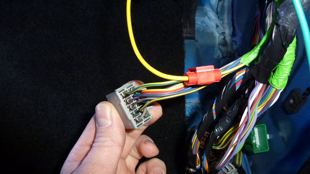
I will add some more pictures to better show where the the connector is in the BCM tonight as I just realized I don't have any that show the face of the BCM.
To get the marker lights to work you need to tap into the parking light circuit.
With the stock power fold mirrors there will be a VT color wire in pin 11 that was for the puddle lamps (interior light circuit).
As best as I could tell when I did my research and based on how these mirrors work on playing with a F250/350 on the dealer lot, pin 11 for the F150 Power Scope mirrors needed to have both an feed from the puddle lamp circuit and the parking light circuit.
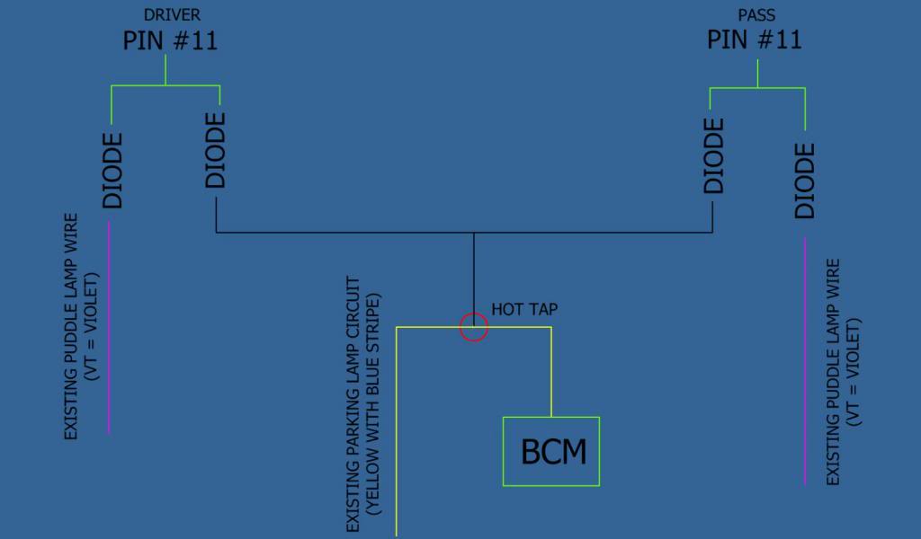
1) Went to the BCM and located the plug that had the parking light circuit from the wiring diagrams. I then did a hot tap connection to it. At the BCM the connector that has the PARKING LIGHT CIRCUIT has a wire that is YELLOW WITH A BLUE STRIPE.
My pictures seems to make the strip look like is is kind of green, but you are looking for the YE-BU wire. From the red hot tap is my Yellow wire that I tie into the passenger and driver run wires but you can't see that.
2) I then ran a new (in my case the yellow wire) from the drivers side to the BCM area (it is located in the passenger side kick panel) and from the passenger side mirror to the BCM area. I then connected the hot tap lead wire to both of these new "out to mirror" run wires together.
3) I then disconnected the existing VT wire from pin #11
4) I put a diode (1N4007 1 Amp 1000V) on the end of each of MY NEW parking light to mirror wires and on each of the now disconnected VT (puddle) lamp wires.
4a) The diode was a suggestion from the guys in my electrical dept to keep any chance of pushing current in the wrong direction since I was combining two POWER SOURCES. The lamp SHOULD only draw from one source at a time as you are not increasing voltage to the lamps only add two sources for the voltage to come from. I don't know if you actually need the diodes or not and I could not tell from the wire diagrams that I had if they were required. The wire diagrams seem to show just joining both the puddle lamp circuit and the parking light circuit together. The diode will not hurt so I thought it was a good idea.
5) Then I combined the VT (puddle lamp) & my new (yellow) parking light circuit together, after the diodes, and then added a new crimp connector to the combined wire and re-installed back into pin #11 on the mirror connector on both sides of the truck.
It is hard to see in the picture but under the heat shrink tube on both the VT wire and YE wire is the diode. They were twisted together and onto a new wire that goes to the pin #11 The connection was then covered in paint on electrical tape. (Twisted soldered wire and paint on electrical tape = bumpy look.......plus I can't solder worth a ****)
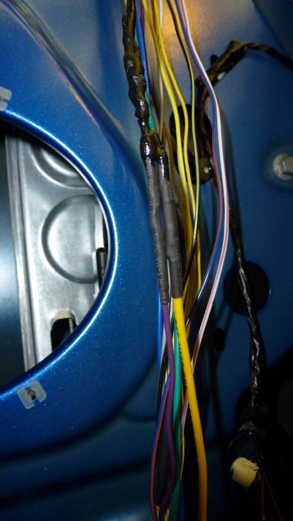
The lights now function just like they did at the dealer on the F250/350 Super Duty Power Scope Mirrors
The lower bulb is puddle/marker the upper bulb is signal/unlock flash.
(SEE MY PREVIOUS POST ABOUT ALL THE FUNCTIONS THE LIGHTS ON THE MIRRORS SHOULD DO)
My mirror lights now function just like they should.
To get the marker lights to work you need to tap into the parking light circuit.
With the stock power fold mirrors there will be a VT color wire in pin 11 that was for the puddle lamps (interior light circuit).
As best as I could tell when I did my research and based on how these mirrors work on playing with a F250/350 on the dealer lot, pin 11 for the F150 Power Scope mirrors needed to have both an feed from the puddle lamp circuit and the parking light circuit.
1) Went to the BCM and located the plug that had the parking light circuit from the wiring diagrams. I then did a hot tap connection to it. At the BCM the connector that has the PARKING LIGHT CIRCUIT has a wire that is YELLOW WITH A BLUE STRIPE.
My pictures seems to make the strip look like is is kind of green, but you are looking for the YE-BU wire. From the red hot tap is my Yellow wire that I tie into the passenger and driver run wires but you can't see that.
2) I then ran a new (in my case the yellow wire) from the drivers side to the BCM area (it is located in the passenger side kick panel) and from the passenger side mirror to the BCM area. I then connected the hot tap lead wire to both of these new "out to mirror" run wires together.
3) I then disconnected the existing VT wire from pin #11
4) I put a diode (1N4007 1 Amp 1000V) on the end of each of MY NEW parking light to mirror wires and on each of the now disconnected VT (puddle) lamp wires.
4a) The diode was a suggestion from the guys in my electrical dept to keep any chance of pushing current in the wrong direction since I was combining two POWER SOURCES. The lamp SHOULD only draw from one source at a time as you are not increasing voltage to the lamps only add two sources for the voltage to come from. I don't know if you actually need the diodes or not and I could not tell from the wire diagrams that I had if they were required. The wire diagrams seem to show just joining both the puddle lamp circuit and the parking light circuit together. The diode will not hurt so I thought it was a good idea.
5) Then I combined the VT (puddle lamp) & my new (yellow) parking light circuit together, after the diodes, and then added a new crimp connector to the combined wire and re-installed back into pin #11 on the mirror connector on both sides of the truck.
It is hard to see in the picture but under the heat shrink tube on both the VT wire and YE wire is the diode. They were twisted together and onto a new wire that goes to the pin #11 The connection was then covered in paint on electrical tape. (Twisted soldered wire and paint on electrical tape = bumpy look.......plus I can't solder worth a ****)
The lights now function just like they did at the dealer on the F250/350 Super Duty Power Scope Mirrors
The lower bulb is puddle/marker the upper bulb is signal/unlock flash.
(SEE MY PREVIOUS POST ABOUT ALL THE FUNCTIONS THE LIGHTS ON THE MIRRORS SHOULD DO)
My mirror lights now function just like they should.
Last edited by MrCdnVegas; 03-22-2014 at 06:31 PM.
The following 4 users liked this post by MrCdnVegas:
03-20-2014, 02:14 PM
#76
Member
Body Control Module
It is the in cab control box /fuse box in the passenger side foot well.
More than just a fuse box as there are electronics and such in side of it not just fuses.
I will take a picture tonight.
It is the in cab control box /fuse box in the passenger side foot well.
More than just a fuse box as there are electronics and such in side of it not just fuses.
I will take a picture tonight.
The following users liked this post:
NASCAR9 (03-20-2014)
03-24-2014, 04:02 PM
#78
Wolf_FX4,
TASCA was very good to me when I ordered my mirrors and caps.
I took MrCdnVegas advice on the Motor Craft link for the wiring on my truck(2012). I'm have issues with IE11 not be able to display the wiring diagrams. Motor Craft has been helpful though. Tech told me I need to either use IE 8 or 9 or try compatibility mode. We'll see tonight.
Also Google Chrome will not work at all.
I also removed my passenger kick panel over the weekend, damn there's
a lot of wires.
03-25-2014, 02:11 PM
#79
Well I tried last night to downgrade my home pc to level that would work on the MotorCraftService.Com web site with zero luck. Seems Ford does not update their software on any kind of regular basis. This may be due to their dealer networks not being able to keep up.
At this point I've given up. I'll try and see if my local dealer will help(not holding my breath).
At this point I've given up. I'll try and see if my local dealer will help(not holding my breath).
03-26-2014, 10:13 AM
#80
Member
NASCAR9
I just looked at my computer.
I'm running IE 8.
I know that it would not work with Google Chrome.
I know that you need to have adobe installed,and need to allow pop up's for the motorcraft site.
I also have SVG installed and shockwave.
I just looked at my computer.
I'm running IE 8.
I know that it would not work with Google Chrome.
I know that you need to have adobe installed,and need to allow pop up's for the motorcraft site.
I also have SVG installed and shockwave.