When you click on links to various merchants on this site and make a purchase, this can result in this site earning a commission. Affiliate programs and affiliations include, but are not limited to, the eBay Partner Network.
mft, sync2. i have the screen and apim, mini usb cable, media interface control module, 8" bezel, the maps on an sd card and a custom harness. my total cost was $636. that's what i want in my pocket after shipping and any fees for payment methods. i'll post up a thread tonight after work in the classifieds with photos of everything.
Starting to take things apart and get ready for install and have a question about the ACM splice... specifically ACM splice 6 to APIM 51 and ACM splice 19 to APIM 52. In looking at the ACM connector, I have no wires in 6 and 19 (pic below)... Is "Satellite Digital Radio" HD radio or Sirius? My ACM has Sirius but not HD radio...
My truck is a 2017 so not sure if there is a difference... if there is, are there other wires I need to splice instead to ensure Sirius continues to work?
Those wires are just for travel link. Sirius will work without them. My acm connector didn't have wires in them either. I added the wires into the connector with the little tyco connectors. If you are unsure, look here to determine what should be there. www.revbase.com/BBBMotor/Wd
Those wires are just for travel link. Sirius will work without them. My acm connector didn't have wires in them either. I added the wires into the connector with the little tyco connectors. If you are unsure, look here to determine what should be there. www.revbase.com/BBBMotor/Wd
Anyone get away with not soldering to the pins? I wonder if I could just wrap the wire around the pin and heat shrink it... or use a crimp/heat shrink tube.
I am handy with a soldering iron, its just one more step and something else for me to mess up.
Likely a bit late to help semper noctem but perhaps others. It is not good practice to solder crimped connectors/pins. When crimping pins the mechanical connection is much stronger than either the connector body or the wire. Provided the proper crimping tool is used which is usually called out by the pin manufacturer. Soldered joints have a tendency to crack over time with even the slightest vibrations or movement. When splicing into an existing wire, the connection should be supported on both ends of the soldered joint. Making these connections is described in the Ford repair manuals which by the way are the exact methods used in FAA aircraft repair manuals.
One other observation. The plugs and pins are usually designed to work together. It is standard practice for the female side of a connector to have the pins indented deeper into the housing. Generally the female side contains the powered side of a circuit (or hot side). The pins are recessed to eliminate any chance of short circuiting and causing fire issues should the connection come apart. It should not be necessary to grind, file the housing. If that were true, I'm sure Ford and all others would have long ago had the manufacturer correct the situation.
Hope this keeps a few folks from having mysterious issues down the road.
I'm about to start the same project on my 2016 150 XLT going from the 4" to Sync 3. In following your posts it appears you ended up with something a bit different than post #35. Could you take the time to write a short summation on what changes you made? This thread is amazingly helpful but also somewhat confusing. I too would like to thank all the contributors who posted here.
I'm about to start the same project on my 2016 150 XLT going from the 4" to Sync 3. In following your posts it appears you ended up with something a bit different than post #35. Could you take the time to write a short summation on what changes you made? This thread is amazingly helpful but also somewhat confusing. I too would like to thank all the contributors who posted here.
I'll let semper summarize his differences but thought it might help to share mine as well... I have a 2017 XLT with 301a package. Everything in post #35 is the same but my exceptions are as follows:
Pin 6 and 12 from the 4.2" screen connector are pinned to 14 and 15, respectively. Meaning, Pin 6 from 4.2" screen to ACIM pin 14 and pin 12 from 4.2" screen to ACIM pin 15. This is needed if you have a rear camera.
You might not have ACM pins 6 and 19 to splice to ACIM 51 and 52. I did not have pins 6 and 19 in my ACM.
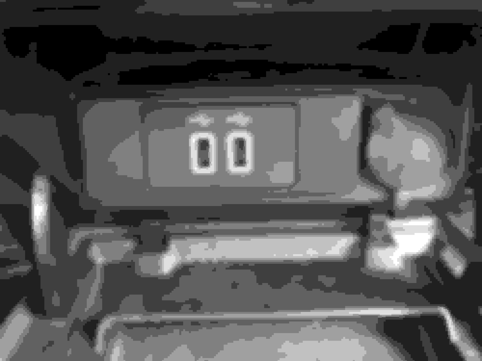
The Media Hub being referred to is the connector that goes into the new USB Hub you have to get if you want to use Car Play/Android Auto. Some folks refer to it as WPT-1239... the Ford PN is CU2Z-14S411-AA.
Thought I would ad the instructions for connectors
Originally Posted by nerdh3rd
Everything is working with Sync 3 at this point besides single tapping on radio and XM presets to change the channel. The button press beep and half second pause work, but the channel never actually changes. Using the steering wheel controls and the hardware tuner **** on the bezel work fine for changing stations, though. Still trying to work out the preset issue.
I've updated my spreadsheets to account for the Sync 3 USB hub wiring (excuse the crude media hub connector picture, I couldn't find one from the manual and had to "make" one) -
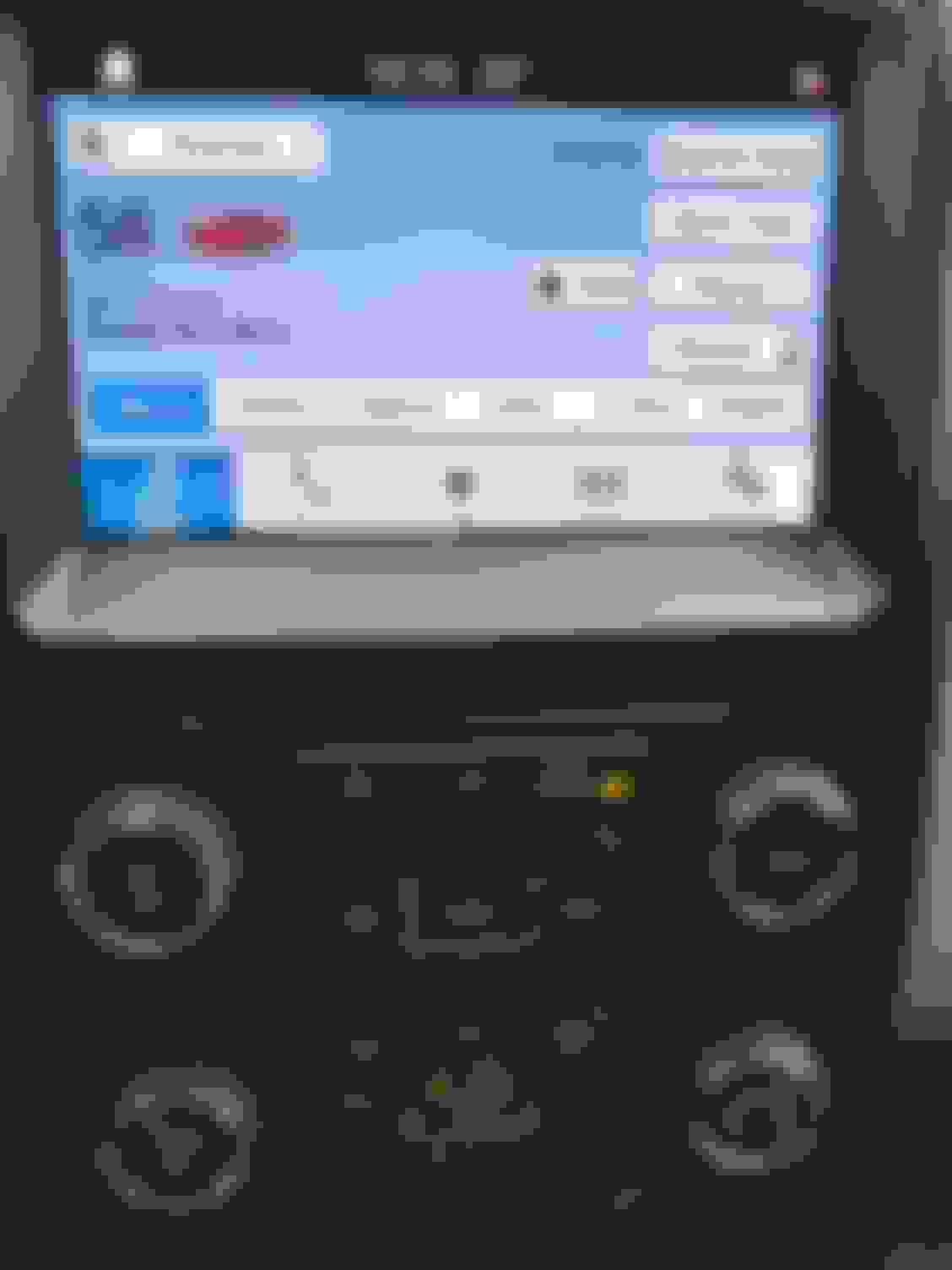
Here are a few pictures of the USB hub/adapter and the Sync 3 screen:
Part numbers for Sync 3 related items:
USB Hub with White LED - GJ7Z-19A387-B
USB Hub with Blue LED - HC3Z-19A387-B
USB Hub bezel adapter - GC3Z-19C149-A
WPT1239 pigtail (power for USB hub) - CU2Z-14S411-AA
The USB hub P/Ns listed are for the CarPlay capable hub.
Here is a link to the AMP connector instructions. Install, remove pins etc.
Likely a bit late to help semper noctem but perhaps others. It is not good practice to solder crimped connectors/pins. When crimping pins the mechanical connection is much stronger than either the connector body or the wire. Provided the proper crimping tool is used which is usually called out by the pin manufacturer. Soldered joints have a tendency to crack over time with even the slightest vibrations or movement. When splicing into an existing wire, the connection should be supported on both ends of the soldered joint. Making these connections is described in the Ford repair manuals which by the way are the exact methods used in FAA aircraft repair manuals.
One other observation. The plugs and pins are usually designed to work together. It is standard practice for the female side of a connector to have the pins indented deeper into the housing. Generally the female side contains the powered side of a circuit (or hot side). The pins are recessed to eliminate any chance of short circuiting and causing fire issues should the connection come apart. It should not be necessary to grind, file the housing. If that were true, I'm sure Ford and all others would have long ago had the manufacturer correct the situation.
Hope this keeps a few folks from having mysterious issues down the road.
For a DIY garage project, I'm not too worried about passing FAA regulations. My homemade harness has been great for almost a year and has survived several temperature fluctuations from fall through winter and spring/summer. The harness should not have excessive movement once installed if it is routed and secured properly.
As for filling the connector, that was incorrect observation on my part, however it should be noted that while the crimp style pins do fit, the female side connector does not come on any component from Ford in that configuration; it is designed to be on pins soldered directly to a circuit board. I would bet that a connector designed specifically for the crimp style pins would look different and have more prominent slots for the pins.
Sorry if I offended you (nerdh3rd) I certainly didn't intend to. I totally respect your hard work and contributions and I thank you for your efforts. My intentions was to explain why things are done as they are (recessed pins)and hopefully eliminate any difficulties two or three years down the road. I can think of nothing worse than a system shutting down when it becomes an oldie but goody truck due to a loose or broken connections. (The FAA reference was simply to let folks know where the info comes from and why things are done in a certain way.) I was just trying to contribute and help others who take this on. These are very expensive vehicles and there is a fair amount of risk involved in doing this. Enough that Ford has issued a bulletin warning on this subject that this mod is not approved. Should the vehicle burn down or some person buy it and have trouble at a later date they will be on their own. Again, I apologize if I offended you.
Sometimes I seem to put my management/teacher hat on and it comes across much different than I intended. That the risk of posting on these sites I guess.

 06-14-2017, 10:53 AM