When you click on links to various merchants on this site and make a purchase, this can result in this site earning a commission. Affiliate programs and affiliations include, but are not limited to, the eBay Partner Network.
Not the actual number of times but telling you it is happening multiple times and each time sets a code with a serial number. Okay example Mercedes has codes just like that. Mercedes the tech is able to click on each code and get live data at each one. B272C-10, B272C-70, B272C-60.... Etc... Mercedes only goes to 100 by 10s B272C-xxx. Good luck, if you have access to live data should be pretty simple to diagnose.
Not the actual number of times but telling you it is happening multiple times and each time sets a code with a serial number. Okay example Mercedes has codes just like that. Mercedes the tech is able to click on each code and get live data at each one. B272C-10, B272C-70, B272C-60.... Etc... Mercedes only goes to 100 by 10s B272C-xxx. Good luck, if you have access to live data should be pretty simple to diagnose.
Ok thanks for dumbing down for me...lol...I smell what your cooking....Forscan I can see live data like the temps, commands, and it even shows when it faults out. Once it faults out I check the code and get the same code over and over, and even in the beginning. Here is my first post when I started trying to fix https://www.f150forum.com/f38/cimate...-codes-370619/ even in this post I was getting it and another code but its gone and all I get is the current one.
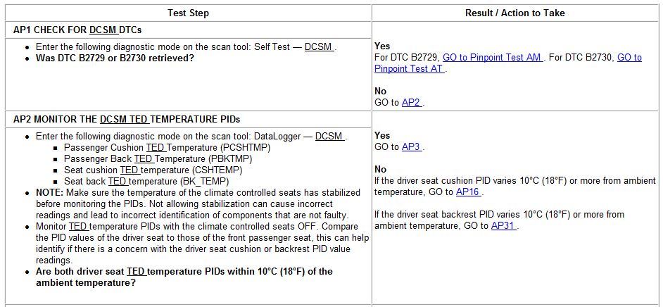
Here are the pinpoint tests for your specific code. All of this rests on IDS diagnostics/pids so there may be some variation if using Forscan, that you will have to determine on your own.
PINPOINT TEST AP: DTC B272C
NOTICE: When taking measurements at Dual Climate Controlled Seat Module (DCSM) harness connectors, do not insert the electrical probes into the female connector pins. Inserting the probes into connector pins can cause intermittent or open electrical connections after reassembly resulting in Diagnostic Trouble Codes (DTCs) and system failure. Touching the tip of these connector pins is recommended instead.
NOTE: If a seat equipped with a seat mounted side air bag is being repaired, the Supplemental Restraint System (SRS) must be depowered.
Turn all vehicle accessories OFF.
Turn the ignition OFF.
At the Body Control Module (BCM), located below the RH side of the instrument panel, remove the cover and RCM fuse 36 (10A) from the BCM .
Turn the ignition ON and monitor the air bag warning indicator for at least 30 seconds. The air bag warning indicator will remain lit continuously (no flashing) if the correct RCM fuse has been removed. If the air bag warning indicator does not remain illuminated continuously, remove the correct RCM fuse before proceeding.
Turn the ignition OFF.
NOTE: The air bag warning lamp illuminates when the Restraints Control Module (RCM) fuse is removed and the ignition switch is ON. This is normal operation and does not indicate an SRS fault.
Start with these tests and report back what you find and I'll post the relevant procedures from there.
I will retry this when I get a chance and see what I find and even remember to take pics of everything. Like mentioned before Ive watched temps on the drivers seat, the time the test was done both cushions started at 100 due to sitting outside in this lovely weather and on heat the bottom cushion I seen 200+ at the highest heard the fan kick on and start dropping before it stopped, while the backrest stayed at 100. The cooling mode it was the same result except the bottom temp went down. I do appreciate the process of making me think this is what I need so thanks again to all that chimes in.
Ok heres what the PIDS show, and a pic of the code there is heat and cool cycles with the drivers showing the fault set and the back rest temp dont move. On the pass side seat you can hear and feel the fans run but only the bottom cushion on the drivers side
Besides not being able to make out your pictures, that 272c-60 code could possibly equal what the very first question asks, "Was B2729 or B2730 retrieved?"
Not going to be able to help you, these pinpoint tests rely on IDS for accuracy, while Forscan is kewl and does a lot of stuff it's still a beta program, diagnostics would be hit/miss.
Time to hit the dealer if you can find one with a tech that knows his stuff.
.
No I havent seen them codes yet and sorry about the quality as on a 23" screen they are readable. I did a self test just now and did get B103c thermoelectric open load and as bad as it sounds there is not a tech around here I trust.
Okay, I see temps. Little less blurry, would be cool.
Could you label the pics? Like ambient temp passenger side, ambient temp driver side, unplugged passenger side, plugged in passenger side, same with drivers side.
Can you measure resistance of the two components while unplugged using the good side side as a known good? Work your way up to the DCSM, of course things have to be unplugged.
If you have a DVOM start testing using passenger side vs driver side.
Narrowing down to PINS 5 and 8 wiring for the temp sensors. Make sure at ambient they are identical.
Last edited by Sarkyman2000; 07-13-2017 at 05:35 PM.
No I havent seen them codes yet and sorry about the quality as on a 23" screen they are readable.
You have a screen capture program built into Windows called "Snipping tool" If you type that in the search bar then create a shortcut to your task bar you can snip a perfect screen shot then upload it.
.
Im sorry about the drunk vision pics as I dont have a laptop and was taken away from the monitor zoomed from phone....As far as the order of pics they go in this order, pic of code, both seats on cool. Under the code pic is the start of heat cycle, almost peek of the heat cycle, then it seeing the fault, and then setting the code and shutting down if that makes sense. Yes I will do some testing as you stated probably be Monday as I have someone that can run/read a DVOM better than me to be sure and thanks everyone for the help. Ambient temp of seats is around 100 like in the pics of back TED

 07-11-2017, 02:15 PM


 ..Forscan I can see live data like the temps, commands, and it even shows when it faults out. Once it faults out I check the code and get the same code over and over, and even in the beginning. Here is my first post when I started trying to fix https://www.f150forum.com/f38/cimate...-codes-370619/ even in this post I was getting it and another code but its gone and all I get is the current one.