When you click on links to various merchants on this site and make a purchase, this can result in this site earning a commission. Affiliate programs and affiliations include, but are not limited to, the eBay Partner Network.
That's a great idea. The OP used the factory Ford wiring harness. I already have that. I really like the LVJ harness. I may contact them about getting just a harness. If that doesn't work out, then I will reach out to Brett. Just saw his new 15-conductor wire harness and it looks great. Just don't know if he can source the plug for the back of the Ford switches. Thanks for the input.
No problem. I've been researching installing the upfitters for a while. Just thought I'd share the LVJ stuff that I found. It sure would make the install a hell of a lot easier. Brett does make very nice stuff and is great to deal with if you haven't before. I haven't seen his harness yet but I'd like to.
Where are you gonna pull keyed power from? A fuse tap?
Still working on where to pull the keyed power from. Somewhere on the driver side of the truck preferably. A fuse tap, would be ideal so that I can minimize the wire splicing. I still think I will need to splice for at least the illumination. May also need to splice for the keyed power. Grounding without a splice will be fairly easy I believe. but still working on my entire wiring game plan.
I could be wrong but the keyed power and illumination are the same?
"This might help. Third pin discription that is cut off is accessory power that is key powered, its what illuminates the Aux letters in the switch. For how you have it set up in YOUR diagram, the only pins you need to use right now are:
PIN #2 Ground
PIN #3 Accessory Power (any wire that comes on with the key)
PIN #7 AUX 1 ( to 86 on relay )
PIN #8 Battery power ( constant + )"
No, keyed power and illumination aren't the same thing. The illumination wire (violet w/grey tracer) needs to spliced into the illumination circuit so it will light up with the rest of the dash and dim correctly. If you wire this to a keyed source the switches will illuminate whenever the switch is on and won't dim.
Where you have "positive power +" will be either constant from the battery OR keyed switched power. You shouldn't have a constant + AND a switched (keyed) + to the switches.
Also, the diagram I posted shows the following:
PIN 1: AUX 4
PIN 2: Illumination
PIN 3: Ground
PIN 5: AUX 3
PIN 6: AUX 2
PIN 7: AUX 1
PIN 8: Positive
Thanks jp360cj for clearing that up. That drawing isn't mine, just one I found in another upfitter thread.
Where did you pull keyed and illum power from by chance?
Check your manual and look at the fuses listed. I had two spare unused fuses that I used an "add a fuse" to tap into. One was for constant power and one was for key-on power. the key-on power doesn't shut off until I open the door (like the radio).
I use the constant and key on to power my dashcam as well as control a couple of relays running to my switches. However the main power for the relays hooked up to my switches are a direct hardwire to the power distribution box (fused of course).
Thanks jp360cj for clearing that up. That drawing isn't mine, just one I found in another upfitter thread.
Where did you pull keyed and illum power from by chance?
I didn't use keyed power. I tapped into the PDC (fuse/relay box) under the hood to power the switches so they are hot all the time. I like to be able to run lights without the switch on. For illumination I used a wire tap at the dimmer switch.
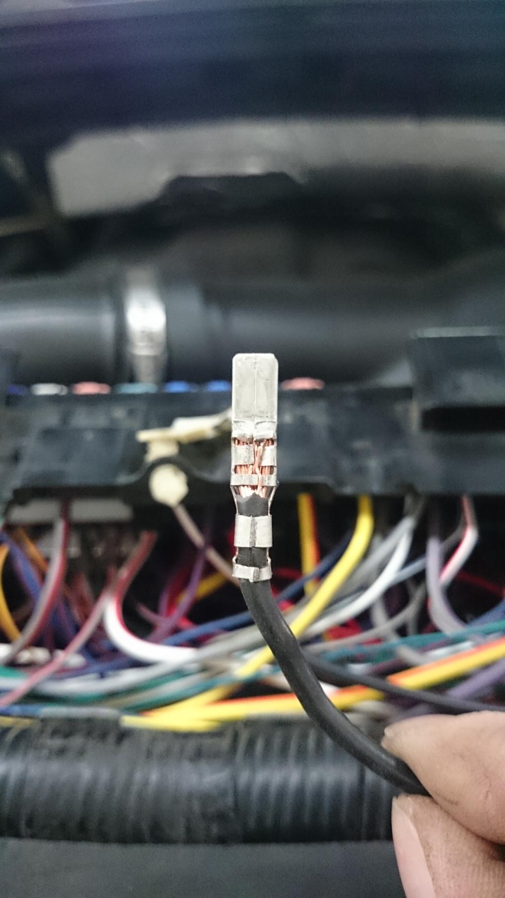
[QUOTE=The Grizz;3981453]So i have had a question about this and thought I should add some more info that I forgot to detail.
For the wires added into the engine compartment fuse box I got a male spade for none other then a GM dealership ( only because they had a good selection ) that where the same size as the factory Ford one's ( my Ford dealer didn't have them, go figure). Once crimped onto the new wires, you locate the corresponding spot on the underside of the top half of the fuse box and push it into the slot. Once you have all the wires pushed in, secured and fuse box snapped back into place take a pair of needle nose pliers and give each spade a gentle tug to make sure they are up as far as they go.
I realize this is an older thread, however it's great information and I used it for a reference for my install. The GM part number for the spade I used is 7114-4121-02. There are several different spades according to the wire gauge used but the part numbers are similar so it should be easy to reference. Thanks for the help Grizz.

 07-06-2016, 11:46 AM