When you click on links to various merchants on this site and make a purchase, this can result in this site earning a commission. Affiliate programs and affiliations include, but are not limited to, the eBay Partner Network.
I ended up going a different direction after I found an overhead custom panel. I didn't really love the idea putting the switches in the cubby and having to modify so much. Obviously, you have to make up your own relay kit as this is just the mount plate and switches.
Anyway, I'll add this for anyone looking for an alternative, not trying to threadjack. Just got them installed today.
How the kit arrives. You can also get a 6 switch option
It isn't quite that simple. Do some searching on the wiring of the upfitter switch. The switch puts out a ground connection when the switch is engaged, so the relays need to be wired in differently than a normal switch like the rigid lights come with. Normally when wiring a switch, the switch puts the positive power to the relay. The upfitter switches will put the negative to the relay. The relays will have to be rewired so that they have constant positive power, and when the upfitter switch connects the negative, the relay will engage.
Does anyone know if this is correct? The wiring diagram I have shows differently. I'm asking because I want a switch to control aux back up lights, but also want them to come on with the factory reverse lights. If the upfitter switches the ground side, then I'll have to another relay, if it switches the positive then I can just tap into it with a diode
Originally Posted by The Grizz
Looks similar but not what I used, if you go to post #50 you will see a pic of the male spade connector I used.
These will work perfectly if you can get them......
Does anyone have details or instructions on what changes need to be made to a rigid harness with relay to work with the unfitted switches? Any detail would be greatly appreciated. Thank you in advance.
Does anyone have details or instructions on what changes need to be made to a rigid harness with relay to work with the unfitted switches? Any detail would be greatly appreciated. Thank you in advance.
You will at least need a connector to fit the back of the upfitter switches. Its just one square-ish multi pin connector for all 4 switches. One wire for switched in, one for illumination, a ground, and 4 switched outs. You would still wire the rigid relay to the battery and bring switched power from the upfitter. There may be extra wires in the rigid harness that you wouldn't need.
You will at least need a connector to fit the back of the upfitter switches. Its just one square-ish multi pin connector for all 4 switches. One wire for switched in, one for illumination, a ground, and 4 switched outs. You would still wire the rigid relay to the battery and bring switched power from the upfitter. There may be extra wires in the rigid harness that you wouldn't need.
I have the connector from the Ford harness and I have been digging into it. I am trying to find the pins for it and the relay pack. I may just end up re-buying the harness and go from there.
I have the connector from the Ford harness and I have been digging into it. I am trying to find the pins for it and the relay pack. I may just end up re-buying the harness and go from there.
Does the connector have the factory colored wires in it? Or do you need to know the actual pinout? I'll see if I can find the wiring diagram I used.
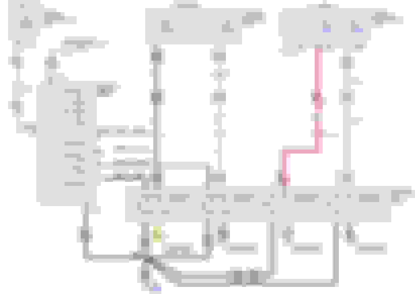
Here is the diagram I used. I think the numbers next to the wires at the switch are the pin numbers. You can verify them with an ohmmeter. If you need me to walk through that let me know.
Yeah. I have got all of that. Thanks. I have read through multiple threads. I am just trying to figure out if there is a way for my to get some new terminal pins that match the ones Ford used. I would rather have one complete wire with no breaks instead of soldering. I may end up having to solder though.
Edit: nvm, just saw your other thread. You already have switches mounted. Maybe contact Brett at KustomFX and see if he will make and sell you a harness. If I remember correctly he was hinting at doing something like that. If not contact the guy in the first link. He obviously makes plug and play harnesses with relay boxes for the upfitter switches. That will be the route I am gonna go. Then I will try to plastic weld the switches to the dash piece as opposed to epoxy.
Last edited by squidpocalypse; 07-06-2016 at 11:08 PM.

 01-31-2016, 12:26 AM