

Can smart charge be disabled?


Joined: Jun 2014
Posts: 31,719
Likes: 12,550
From: Nowhereville, Barton City Michigan
Some injunear must be patting himself on the back for that one, as in OCD. Whatever the savings, they must be pretty small.
Sorta reminds me of spending a dollar to save a dime.
I'm with Lee on this one.

But, I already paid for it, might just as well live with it. I wonder what this system is doing to my new non-silver calcium battery.

Member
Joined: Feb 2013
Posts: 26,680
Likes: 6,253
From: Big Easy
Guess I may as well post how the system operates to alleviate any questions.
Principles of Operation
Charging System
The PCM-controlled, or Smart Charge charging system determines the optimal voltage setpoint for the charging system and communicates this information to the voltage regulator. The Smart Charge charging system is designed to set 1 of 6 DTCs any time a charging system fault is present. All of the DTCs can set continuous faults, but not all DTCs set as on-demand faults.
This system uses 2 communication lines between the PCM and the generator/voltage regulator. Both of these communication lines use Pulse-Width Modulation (PWM). The generator communication (GENCOM) line communicates the desired setpoint from the PCM to the voltage regulator. The generator monitor (GENMON) line communicates the generator load and error conditions to the PCM. The GENCOM command is only sent by the PCM when it is necessary to adjust the voltage setpoint. If the setpoint does not need to be changed, several seconds may elapse between PCM GENCOM commands. This normal operation appears in the PID as occasional bursts of pulse-width commands. The third pin on the voltage regulator, the "A" pin, is a circuit dedicated to monitor or sense battery voltage.
The PCM simultaneously controls and monitors the output of the generator. When the current consumption is high or the battery is discharged, the PCM raises engine speed as needed to increase generator output. The generator charges the battery and at the same time supplies power for all of the electrical loads that are required. The battery is more effectively charged with a higher voltage when the battery is cold and a lower voltage when the battery is warm. The PCM is able to adjust the charging voltage according to the battery temperature, calculated by using a signal from the Intake Air Temperature (IAT) sensor. The PCM also uses other inputs to control charging system voltage such as the Vehicle Speed Sensor (VSS) and Engine Coolant Temperature (ECT). The voltage setpoint is calculated by the PCM and communicated to the voltage regulator by the GENCOM circuit based on the needs of the vehicle and the conditions.
The PCM turns off the generator during cranking to reduce the generator load and improve cranking speed. Once the engine starts, the PCM slowly increases generator output to the desired voltage.
The PCM reports any charging system faults and sends a message through High Speed Controller Area Network (HS-CAN) to the Body Control Module (BCM). The BCM controls the charging system warning indicator by sending a message over the Medium Speed Controller Area Network (MS-CAN) to the Instrument Panel Cluster (IPC). The IPC then controls charging system warning indication based on the message from the PCM through the BCM . The status of the PCM charging system warning indicator and/or message can be confirmed by viewing PCM PID generator fault indicator lamp (GENFIL). Any charging system fault detected by the PCM results in 1 or more DTCs being set and the PID GENFIL having a status of On. If equipped with a charging system warning indicator, the IPC turns the indicator on or off. If equipped with a message center, the IPC displays a CHECK CHARGING SYSTEM message. When the ignition is ON and the engine is off on vehicles equipped with a message center, the CHECK CHARGING SYSTEM message may not be displayed.
Under certain circumstances, the charging system may have a concern, but still keeps the battery charged and the vehicle running. GENCOM is normally used to initiate charging, but the generator may charge with a fault in this circuit. If the engine operates at more than 2,000 rpm momentarily, the generator may self-excite or start charging on its own. The charging system warning indicator is illuminated and/or CHECK CHARGING SYSTEM message is displayed, and the generator operates in a default mode (approximately 13.5 volts) until the engine is turned off. When the engine is restarted and the engine operates at more than 2,000 rpm momentarily, the generator may again self-excite and again the charging system warning indicator is illuminated and/or CHECK CHARGING SYSTEM message is displayed.
Load Shed Operation
NOTICE: When the Body Control Module (BCM) is being programmed, connect an external battery charger to make sure that the module programming is completed without the interruption due to the load shedding feature becoming active. The external battery charger must maintain a system voltage above 13 volts. This may require a charger setting higher than the lowest charge setting. The external battery charger negative connection must be made to an engine or vehicle chassis ground and not the negative battery terminal. If the connection is to the negative battery terminal, load shedding cannot be prevented from being invoked and module programming may be corrupted. After charging has begun, start the engine to clear any load shed states and then turn the engine off and proceed with programming.
NOTE: To maintain correct operation of the load shed system, any electrical devices or equipment must be grounded to the engine or chassis ground and not the negative battery terminal. A connection to the negative battery terminal may cause an inaccurate measurement of the battery state of charge and may cause incorrect load shed system operation.
This vehicle is equipped with load shed strategy. The Body Control Module (BCM) monitors system voltage to the BCM and the Power Steering Control Module (PSCM) as well as the battery state of charge using the battery current sensor attached to the negative battery cable.
Engine Off Load Shed
The BCM uses the battery current sensor to keep track of the battery state of charge. The battery current sensor is a Hall-effect sensor attached to the battery ground cable. When the engine is off, and the BCM determines the battery state of charge is below 40% or 10% of the charge has been drained or 45 minutes have elapsed, a load shed message is sent over the Controller Area Network (CAN). This message turns off the audio/navigation system to save the remaining battery charge. Under this condition, the Front Display Interface Module (FDIM) displays SYS OFF TO SAVE BATT (without navigation) or BATTERY SAVER � SYSTEM OFF PLEASE START THE ENGINE (with navigation) to notify the driver that battery protection actions are active.
Engine off load shed occurs when the engine is not running, and the ignition is in the ACC or RUN position. To clear the load shed state, restart the engine.
NOTE: To maintain correct operation of the load shed system, any electrical devices or equipment must be grounded to the engine or chassis ground and not the negative battery terminal. A connection to the negative battery terminal may cause an inaccurate measurement of the battery state of charge and may cause incorrect load shed system operation.
When charging the vehicle battery by connecting the charger to the negative battery terminal is necessary , such as when using a combination battery charger and battery tester/analyzer, like the GR 1 190 V3.0 Intelligent Diagnostic Charger, the BCM will not immediately update the battery state of charge. In this instance, after charging, you must carry out the Battery Monitoring System (BMS) Reset using the scan tool. This reset is needed for proper engine off load shedding and to prevent invoking of engine off load shedding earlier than normal.
NOTE: If the reset is not carried out, when the battery is charged by connecting the charger to the negative battery terminal, it takes approximately 8 hours for the BCM to learn the new battery state of charge. During this 8 hour period, the vehicle must be undisturbed, with no doors opened or keyless entry button presses. If the vehicle is used before the BCM is allowed to learn the new battery state of charge, engine off load shedding can still occur and a message may be displayed.
When charging the vehicle battery by connecting the charger to engine or chassis ground , the negative charger clamp must be connected to an unpainted chassis surface or a solid engine component such as a generator mount or engine lifting eye. In this instance, after charging, the BMS Reset is not required . Through this method of charging the BCM will update the battery state of charge during the charging process.
When the ignition is in the RUN position and load shed occurs, the IPC message center displays either TURN POWER OFF TO SAVE BATT (base message center) or TURN POWER OFF TO SAVE BATTERY (optional message center). The audio/navigation system will shut down after the message center displays it's warning.
If a fault occurs with the battery current sensor or circuit(s), the only engine off load shed strategy is a 45 minute timer. After 45 minutes have elapsed, the audio/navigation system turns off. To clear the load shed state, restart the engine.
Engine Running Load Shed
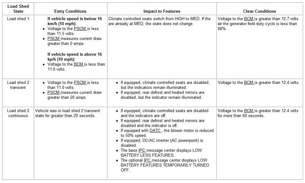
When the BCM and/or PSCM voltage is low, with the engine running, a message is sent by the BCM to either minimize or shut down the climate controlled seats, rear defrost, heated mirrors and Dual Automatic Temperature Control (DATC) blower motor to improve system voltage. Under this condition, the IPC message center displays either LOW BATTERY LESS FEATURES (base message center) or LOW BATTERY FEATURES TEMPORARILY TURNED OFF (optional message center) to notify the driver that battery protection actions are active.
There are 3 states of engine running load shed:
Load shed 1
Load shed 2 transient
Load shed 2 continuous
.
Principles of Operation
Charging System
The PCM-controlled, or Smart Charge charging system determines the optimal voltage setpoint for the charging system and communicates this information to the voltage regulator. The Smart Charge charging system is designed to set 1 of 6 DTCs any time a charging system fault is present. All of the DTCs can set continuous faults, but not all DTCs set as on-demand faults.
This system uses 2 communication lines between the PCM and the generator/voltage regulator. Both of these communication lines use Pulse-Width Modulation (PWM). The generator communication (GENCOM) line communicates the desired setpoint from the PCM to the voltage regulator. The generator monitor (GENMON) line communicates the generator load and error conditions to the PCM. The GENCOM command is only sent by the PCM when it is necessary to adjust the voltage setpoint. If the setpoint does not need to be changed, several seconds may elapse between PCM GENCOM commands. This normal operation appears in the PID as occasional bursts of pulse-width commands. The third pin on the voltage regulator, the "A" pin, is a circuit dedicated to monitor or sense battery voltage.
The PCM simultaneously controls and monitors the output of the generator. When the current consumption is high or the battery is discharged, the PCM raises engine speed as needed to increase generator output. The generator charges the battery and at the same time supplies power for all of the electrical loads that are required. The battery is more effectively charged with a higher voltage when the battery is cold and a lower voltage when the battery is warm. The PCM is able to adjust the charging voltage according to the battery temperature, calculated by using a signal from the Intake Air Temperature (IAT) sensor. The PCM also uses other inputs to control charging system voltage such as the Vehicle Speed Sensor (VSS) and Engine Coolant Temperature (ECT). The voltage setpoint is calculated by the PCM and communicated to the voltage regulator by the GENCOM circuit based on the needs of the vehicle and the conditions.
The PCM turns off the generator during cranking to reduce the generator load and improve cranking speed. Once the engine starts, the PCM slowly increases generator output to the desired voltage.
The PCM reports any charging system faults and sends a message through High Speed Controller Area Network (HS-CAN) to the Body Control Module (BCM). The BCM controls the charging system warning indicator by sending a message over the Medium Speed Controller Area Network (MS-CAN) to the Instrument Panel Cluster (IPC). The IPC then controls charging system warning indication based on the message from the PCM through the BCM . The status of the PCM charging system warning indicator and/or message can be confirmed by viewing PCM PID generator fault indicator lamp (GENFIL). Any charging system fault detected by the PCM results in 1 or more DTCs being set and the PID GENFIL having a status of On. If equipped with a charging system warning indicator, the IPC turns the indicator on or off. If equipped with a message center, the IPC displays a CHECK CHARGING SYSTEM message. When the ignition is ON and the engine is off on vehicles equipped with a message center, the CHECK CHARGING SYSTEM message may not be displayed.
Under certain circumstances, the charging system may have a concern, but still keeps the battery charged and the vehicle running. GENCOM is normally used to initiate charging, but the generator may charge with a fault in this circuit. If the engine operates at more than 2,000 rpm momentarily, the generator may self-excite or start charging on its own. The charging system warning indicator is illuminated and/or CHECK CHARGING SYSTEM message is displayed, and the generator operates in a default mode (approximately 13.5 volts) until the engine is turned off. When the engine is restarted and the engine operates at more than 2,000 rpm momentarily, the generator may again self-excite and again the charging system warning indicator is illuminated and/or CHECK CHARGING SYSTEM message is displayed.
Load Shed Operation
NOTICE: When the Body Control Module (BCM) is being programmed, connect an external battery charger to make sure that the module programming is completed without the interruption due to the load shedding feature becoming active. The external battery charger must maintain a system voltage above 13 volts. This may require a charger setting higher than the lowest charge setting. The external battery charger negative connection must be made to an engine or vehicle chassis ground and not the negative battery terminal. If the connection is to the negative battery terminal, load shedding cannot be prevented from being invoked and module programming may be corrupted. After charging has begun, start the engine to clear any load shed states and then turn the engine off and proceed with programming.
NOTE: To maintain correct operation of the load shed system, any electrical devices or equipment must be grounded to the engine or chassis ground and not the negative battery terminal. A connection to the negative battery terminal may cause an inaccurate measurement of the battery state of charge and may cause incorrect load shed system operation.
This vehicle is equipped with load shed strategy. The Body Control Module (BCM) monitors system voltage to the BCM and the Power Steering Control Module (PSCM) as well as the battery state of charge using the battery current sensor attached to the negative battery cable.
Engine Off Load Shed
The BCM uses the battery current sensor to keep track of the battery state of charge. The battery current sensor is a Hall-effect sensor attached to the battery ground cable. When the engine is off, and the BCM determines the battery state of charge is below 40% or 10% of the charge has been drained or 45 minutes have elapsed, a load shed message is sent over the Controller Area Network (CAN). This message turns off the audio/navigation system to save the remaining battery charge. Under this condition, the Front Display Interface Module (FDIM) displays SYS OFF TO SAVE BATT (without navigation) or BATTERY SAVER � SYSTEM OFF PLEASE START THE ENGINE (with navigation) to notify the driver that battery protection actions are active.
Engine off load shed occurs when the engine is not running, and the ignition is in the ACC or RUN position. To clear the load shed state, restart the engine.
NOTE: To maintain correct operation of the load shed system, any electrical devices or equipment must be grounded to the engine or chassis ground and not the negative battery terminal. A connection to the negative battery terminal may cause an inaccurate measurement of the battery state of charge and may cause incorrect load shed system operation.
When charging the vehicle battery by connecting the charger to the negative battery terminal is necessary , such as when using a combination battery charger and battery tester/analyzer, like the GR 1 190 V3.0 Intelligent Diagnostic Charger, the BCM will not immediately update the battery state of charge. In this instance, after charging, you must carry out the Battery Monitoring System (BMS) Reset using the scan tool. This reset is needed for proper engine off load shedding and to prevent invoking of engine off load shedding earlier than normal.
NOTE: If the reset is not carried out, when the battery is charged by connecting the charger to the negative battery terminal, it takes approximately 8 hours for the BCM to learn the new battery state of charge. During this 8 hour period, the vehicle must be undisturbed, with no doors opened or keyless entry button presses. If the vehicle is used before the BCM is allowed to learn the new battery state of charge, engine off load shedding can still occur and a message may be displayed.
When charging the vehicle battery by connecting the charger to engine or chassis ground , the negative charger clamp must be connected to an unpainted chassis surface or a solid engine component such as a generator mount or engine lifting eye. In this instance, after charging, the BMS Reset is not required . Through this method of charging the BCM will update the battery state of charge during the charging process.
When the ignition is in the RUN position and load shed occurs, the IPC message center displays either TURN POWER OFF TO SAVE BATT (base message center) or TURN POWER OFF TO SAVE BATTERY (optional message center). The audio/navigation system will shut down after the message center displays it's warning.
If a fault occurs with the battery current sensor or circuit(s), the only engine off load shed strategy is a 45 minute timer. After 45 minutes have elapsed, the audio/navigation system turns off. To clear the load shed state, restart the engine.
Engine Running Load Shed
When the BCM and/or PSCM voltage is low, with the engine running, a message is sent by the BCM to either minimize or shut down the climate controlled seats, rear defrost, heated mirrors and Dual Automatic Temperature Control (DATC) blower motor to improve system voltage. Under this condition, the IPC message center displays either LOW BATTERY LESS FEATURES (base message center) or LOW BATTERY FEATURES TEMPORARILY TURNED OFF (optional message center) to notify the driver that battery protection actions are active.
There are 3 states of engine running load shed:
Load shed 1
Load shed 2 transient
Load shed 2 continuous
.
Joined: Jun 2014
Posts: 31,719
Likes: 12,550
From: Nowhereville, Barton City Michigan
^^Geez, there's a lot there. Am I right thinking that all that is needed since computers are voltage sensitive?
Looks like I need to change my onboard charger ground to the body/chassis somewhere
Looks like I need to change my onboard charger ground to the body/chassis somewhere


Member
Joined: Feb 2013
Posts: 26,680
Likes: 6,253
From: Big Easy
Welcome to the 21st century. I suggest re-reading the entire post a few times to fully understand, I had to at least 3 times before I realized what caused an electrical failure I had on my truck in the recent past. I have a dash top solar maintainer as many know and I didn't ground it to the chassis/body/block, I went right to the negative battery terminal, didn't take long to kill my battery. I also need to re-route my winch ground cable.
It's really not a big deal, there are plenty of bolting places all over the chassis/block/body to ground something, if you can't find an easily accessible spot, grab a drill.
.
It's really not a big deal, there are plenty of bolting places all over the chassis/block/body to ground something, if you can't find an easily accessible spot, grab a drill.
.
Last edited by RLXXI; Jun 17, 2017 at 06:41 PM.

Thread Starter
Senior Member
Joined: Jul 2009
Posts: 826
Likes: 129
Yes, but a truck should be able to sit for more then a few days without a dead battery. It's happened to me twice. And the bigger problem is after recharging the battery my transmission defaults to 3rd gear. Will not shift up or down. So i have to drive 6 miles in 3rd gear to the local transmission shop to re-program the computer. Good thing I live that close.

King Hater
Joined: Dec 2013
Posts: 6,973
Likes: 874
From: MONTANA
If I could find a good one I would. They are all gone.
You did not answer the question.
Can "smart" charge be disabled?
PS, there is not one thing about this 2013 I like better than the 1995 I had, but there is a whole list of things I like less about the 2013 than the 1995.
Smart charge and EAPS tops the list.
You did not answer the question.
Can "smart" charge be disabled?
PS, there is not one thing about this 2013 I like better than the 1995 I had, but there is a whole list of things I like less about the 2013 than the 1995.
Smart charge and EAPS tops the list.
I guarantee someone with a 95 would trade your straight across for your 13.
5 Year Member

Joined: Feb 2009
Posts: 483
Likes: 98
From: Southeastern Pennsylvania
The only thing on my 13 that I like less than the 97 I had is the dipstick location on the 5.0.
I have long arm, but I can barely reach the sumbitch....
I wonder how many of the people who post about issues with battery charge system have added stuff and grounded direct to the negative battery terminal?
There is a bolt on the fender right next to the battery that is connected to a heavy wire going the the neg terminal. That's where I grounded my addons.
My commute to work is 15 miles, and its about 25/75% highway/local roads, and I have had no issues.
The only time I have seen the battery warning is on the 45 minute timeout.
You can check the battery parameters with data streaming in Forscan.
State of charge, charge/discharge current, battery temp can all be monitored.
My state of charge has been between 80 and 90% everytime I have checked.
My ham radio has a voltmeter function on the display and is connected direct to the battery. My charging voltage runs between 13.0 and 14.1 volts unless I've been on a highway run for several hours.
On several recent trips to Florida, I have seen it drop to 12.9 after running for 4 hours or more.
The amount of fuel this saves on a per vehicle basis is pretty small, bit if you add up a 0.1MPG saving across a deployed fleet of thousands of vehicle, the saving can be significant.

Senior Member
Joined: Dec 2011
Posts: 418
Likes: 32
Nominal voltage on your battery without the engine running is between about 12.5-13v.
The alternator usually outputs between about 13.5-14v on older cars to help the battery recharge faster after a start, and to compensate for voltage drop for high load devices (ie., headlights, factory high power stereo amps, etc.).
Anything designed to run on an automotive 12v system usually has an operating range between about 11.5-15v.
So with all of that in mind, you're wasting energy running the alternator at a higher output when it is not required. Once the battery is charged to a certain level (if it is like other battery chargers, probably in the 95% range) and there's no high load devices running (headlights, heated seats, etc.) running, there's no point in maintaining that 13.8v output when your battery is happy at 12.5-13v and every other device has a fairly wide operating range.