
Adding switches/wiring questions for a complete wiring noob!
 04-20-2014, 01:40 AM
#1

Hello all,
Please excuse me as I know very little when it comes to automotive wiring but I am trying to learn here so any help would be greatly appreciated. I did do a few searches but it seems like for most of you this stuff is pretty common sense and is isn't really discussed or is blown over. My truck is a 2012 stx/
I will be adding some led lights in the bed of the truck with a switch near the tailgate and adding some rigid lights under the rear bumper with a switch in the cab for that. I plan to add some more switches for some interior led's down the road but I figure it would be really similar to what I will be doing with these.
My questions are as follows:
1). Do I run a wire from the battery to the back of the truck for power and split it to the two light setups or can I tie into the towing harness (not sure which pin might be the 12v constant or if it is on only when the truck is on).
2). Do I need to add any in-line fuses, if so what size?
3). I was looking at rocker switches and noticed some list the switch as 15A, 20A, and others with no Amp rating at all. Do the 15A & 20A switches have fuses in them already or do I not need to worry about that? Little confused there.
Thanks again in advance!
 04-20-2014, 08:46 AM
#2
Senior Member

Anytime you run a wire from the pos side of the battery it should be fused. Generally switches will tolerate whatever load you are putting through them for running lights and stuff, unless you get really crazy. If you plan to have the Rigid lights come on with the reverse lights,you will want to run that through a relay. I just did all this on my truck. I'll hunt down the post and put the link in here.
I can't figure out to get the link (I'm on mobile), but it's easy to find. Look in the Electrical and lights forum, it's the post started by BigWhite. Read clear through it, it took us a bit to get it figured out.
Feel free to PM me with questions.
I can't figure out to get the link (I'm on mobile), but it's easy to find. Look in the Electrical and lights forum, it's the post started by BigWhite. Read clear through it, it took us a bit to get it figured out.
Feel free to PM me with questions.
Last edited by jgohlke; 04-20-2014 at 08:50 AM.
The following users liked this post:
The Machine (04-20-2014)
04-20-2014, 09:07 AM
#3

Hello all,
Please excuse me as I know very little when it comes to automotive wiring but I am trying to learn here so any help would be greatly appreciated. I did do a few searches but it seems like for most of you this stuff is pretty common sense and is isn't really discussed or is blown over. My truck is a 2012 stx/
I will be adding some led lights in the bed of the truck with a switch near the tailgate and adding some rigid lights under the rear bumper with a switch in the cab for that. I plan to add some more switches for some interior led's down the road but I figure it would be really similar to what I will be doing with these.
My questions are as follows:
1). Do I run a wire from the battery to the back of the truck for power and split it to the two light setups or can I tie into the towing harness (not sure which pin might be the 12v constant or if it is on only when the truck is on).
2). Do I need to add any in-line fuses, if so what size?
3). I was looking at rocker switches and noticed some list the switch as 15A, 20A, and others with no Amp rating at all. Do the 15A & 20A switches have fuses in them already or do I not need to worry about that? Little confused there.
Thanks again in advance!
Please excuse me as I know very little when it comes to automotive wiring but I am trying to learn here so any help would be greatly appreciated. I did do a few searches but it seems like for most of you this stuff is pretty common sense and is isn't really discussed or is blown over. My truck is a 2012 stx/
I will be adding some led lights in the bed of the truck with a switch near the tailgate and adding some rigid lights under the rear bumper with a switch in the cab for that. I plan to add some more switches for some interior led's down the road but I figure it would be really similar to what I will be doing with these.
My questions are as follows:
1). Do I run a wire from the battery to the back of the truck for power and split it to the two light setups or can I tie into the towing harness (not sure which pin might be the 12v constant or if it is on only when the truck is on).
2). Do I need to add any in-line fuses, if so what size?
3). I was looking at rocker switches and noticed some list the switch as 15A, 20A, and others with no Amp rating at all. Do the 15A & 20A switches have fuses in them already or do I not need to worry about that? Little confused there.
Thanks again in advance!
This linky may help:
http://www.f150online.com/forums/art...-how-pics.html
General electrical best-practices:
- always fuse the circuts as close as possible to the battery - this protects the components AND the wiring.
- always use a relay - regardless of loads switched. Relays can switch huge loads, while allowing you to use nice, small, purty-lookin' control switches and run small wiring into the cab proper ( you still need to fuse anything passing through the firewall for safety though).
- relays allow for some logic - e.g: sensing when the vehicle is OFF to kill the power to the load (in case you forget to turn it off and drain yer battery). You'd use a Power-in-Start-or-Run feed for this. Radio or other accessory feed at the fuse panel - simple Add-a-Fuse to provide this trigger.
- always use wire that is rated for automotive use ( do NOT use zip cord, houshold lamp wire, etc )
-size the wiring and fuses according to your loads:
Auto wiring ( using auto wire with 105* C rate ) - derated for extra safety:
10 AWG : 30 AMP
12 AWG : 20 AMP
14 AWG : 15 AMP
16 AWG : 10 AMP
The load on a circuit should be 80% of the fuse and wire capacity -
Examples-
- Max 16 AMP load on a 12 AWG wire and a 20 AMP fuse.
- Max 12 AMP load on a 14 AWG wire and a 15 AMP fuse.
-always use wire loom (at least) to protect the wiring.
-soldered & shrinkwrapped connections are always preferred for reliability
Lastly - Please try to keep the conversation in yer thread rather than taking it to PM's so others who see it later can also benefit. Much appreciated!
good luck
MGD
Last edited by MGD; 04-20-2014 at 09:14 AM.
The following 4 users liked this post by MGD:
04-20-2014, 10:36 AM
#4
Thanks for the help guys , I really want to learn this stuff! I'm not familiar with relays, just googled it and it looks like I have more reading to do. I've got to add a relay to the tr7 module for an automatic tailgate opening mod I'm doing. They are completely foreign to me and not sure which wires go where. Im sure I'll be back with more questions .
04-20-2014, 02:14 PM
#5
Good mornin' & Happy Easter, thar!
This linky may help:
http://www.f150online.com/forums/art...-how-pics.html
General electrical best-practices:
- always fuse the circuts as close as possible to the battery - this protects the components AND the wiring.
- always use a relay - regardless of loads switched. Relays can switch huge loads, while allowing you to use nice, small, purty-lookin' control switches and run small wiring into the cab proper ( you still need to fuse anything passing through the firewall for safety though).
- relays allow for some logic - e.g: sensing when the vehicle is OFF to kill the power to the load (in case you forget to turn it off and drain yer battery). You'd use a Power-in-Start-or-Run feed for this. Radio or other accessory feed at the fuse panel - simple Add-a-Fuse to provide this trigger.
- always use wire that is rated for automotive use ( do NOT use zip cord, houshold lamp wire, etc )
-size the wiring and fuses according to your loads:
Auto wiring ( using auto wire with 105* C rate ) - derated for extra safety:
10 AWG : 30 AMP
12 AWG : 20 AMP
14 AWG : 15 AMP
16 AWG : 10 AMP
The load on a circuit should be 80% of the fuse and wire capacity -
Examples-
- Max 16 AMP load on a 12 AWG wire and a 20 AMP fuse.
- Max 12 AMP load on a 14 AWG wire and a 15 AMP fuse.
-always use wire loom (at least) to protect the wiring.
-soldered & shrinkwrapped connections are always preferred for reliability
Lastly - Please try to keep the conversation in yer thread rather than taking it to PM's so others who see it later can also benefit. Much appreciated!
good luck
MGD
I have a few follow up questions
1). what amperage fuse and gauge of wire would you recommend for running the two rigid lights and about 13' of LED's
2). Can I just run one power wire from the battery to the back and split that to use as the power source to both the LEDs and the Rigid lightbars?
3). Any idea on how I would wire the circuit/switches for the Ridgid lights If I wanted a switch in the back of the truck AND one in the cab?
As always, the members on this forum never seam to fail me, THANK YOU!!!
04-20-2014, 05:47 PM
#6
Hi.
My answers in Bold below:
Here are some more informative links on relays, etc, with some examples (sorry - lots to read, lol)
www.the12volt.com
http://www.bcae1.com/relays.htm
And more (parts 1 & 3 of a three-section article - part two is AWOL. Multiple pages per section - again a lot to read, but some very good reference / tutorial info fer y'all):
http://www.f150online.com/tech/electrical1.html
http://www.f150online.com/tech/control1.html
Goin' back to stuffing my face now - Happy Easter!
Best of luck!

MGD
My answers in Bold below:
OH MAN!!! This just goes to show you how much of a noob I am in. I'm all sitting here trying to understand how a relay works and it finally dawned on me that its the same damn thing, just smaller, that I used in my retrofit kit from TRS! I get it now and understand what its doing.
I have a few follow up questions
1). what amperage fuse and gauge of wire would you recommend for running the two rigid lights and about 13' of LED's
Can't answer that without the specs. Or, you can figure that out from the electrical spec info already given by the manufacturer, since you have the specs, lol.
2). Can I just run one power wire from the battery to the back and split that to use as the power source to both the LEDs and the Rigid lightbars?
Yep. Just size it (wire gauge and fuse size) to handle to TOTAL load yer running at the back of the truck. So - add them up.
3). Any idea on how I would wire the circuit/switches for the Ridgid lights If I wanted a switch in the back of the truck AND one in the cab?
Without posting a drawing, just picture each SPST switch - with one terminal of each going to a fused positive feed, and the other terminal going to the same coil terminal on the relay - wherever you choose to mount it.The other relay coil terminal will need to be grounded.
Throwing either switch will energize the relay, which will in turn close the contacts and power yer lights.
If you do not choose to wire the switch feeds to a 'switched' power source in the truck as mentioned earlier, you WILL need to remember to turn both switches off or else risk depleting yer battery.
As always, the members on this forum never seam to fail me, THANK YOU!!!
Thankee! Yer welcome!
www.the12volt.com
http://www.bcae1.com/relays.htm
And more (parts 1 & 3 of a three-section article - part two is AWOL. Multiple pages per section - again a lot to read, but some very good reference / tutorial info fer y'all):
http://www.f150online.com/tech/electrical1.html
http://www.f150online.com/tech/control1.html
Goin' back to stuffing my face now - Happy Easter!
Best of luck!
MGD
Last edited by MGD; 04-20-2014 at 06:24 PM. Reason: corrections
04-22-2014, 03:54 AM
#7
Thanks so much MGD for your help and direction.
One last question for now, I've seen it done in some residential lighting where instead of lights going on 100% immediately they gradually light up over a span of a few seconds. I'm not referring to cfl's where they need to warm up, this is a planned thing. Is there some fuse, relay or something that would achieve this result that you know of?
One last question for now, I've seen it done in some residential lighting where instead of lights going on 100% immediately they gradually light up over a span of a few seconds. I'm not referring to cfl's where they need to warm up, this is a planned thing. Is there some fuse, relay or something that would achieve this result that you know of?
Trending Topics
04-22-2014, 06:01 AM
#8
Thanks so much MGD for your help and direction.
One last question for now, I've seen it done in some residential lighting where instead of lights going on 100% immediately they gradually light up over a span of a few seconds. I'm not referring to cfl's where they need to warm up, this is a planned thing. Is there some fuse, relay or something that would achieve this result that you know of?
One last question for now, I've seen it done in some residential lighting where instead of lights going on 100% immediately they gradually light up over a span of a few seconds. I'm not referring to cfl's where they need to warm up, this is a planned thing. Is there some fuse, relay or something that would achieve this result that you know of?
There are several ways to do this:
1. Off-the-shelf.
Example = http://current-usa.com/accessories/ramp-timer-pro/
http://current-usa.com/wp-content/up...V5-Final-1.pdf
2. Microcontroller - e.g. Arduino, running some simple code.
Example = https://learn.sparkfun.com/tutorials/what-is-an-arduino
http://arduino.cc/en/Tutorial/Fade
3. Complete DIY with discrete electronics ( e.g 555-based ramp generator driving a 555-based PWM, driving high-power LED drivers ).
Example = http://forum.allaboutcircuits.com/blog.php?b=378
Given the apparently high current loads of your chosen LEDs this may be a bit costly. The ramp control will be the same - it's the drivers that need to be robust to handle the power. Higher power drivers = more money.
If yer willing to learn this could be a great hobby for you. Microcontrollers and the programming languages that run them are fascinating. And offer the most flexibility, by far. Almost anything you can imagine can be done.
MGD
Last edited by MGD; 04-22-2014 at 06:06 AM.
04-23-2014, 04:47 AM
#9
Hi.
There are several ways to do this:
1. Off-the-shelf.
Example = http://current-usa.com/accessories/ramp-timer-pro/
http://current-usa.com/wp-content/up...V5-Final-1.pdf
2. Microcontroller - e.g. Arduino, running some simple code.
Example = https://learn.sparkfun.com/tutorials/what-is-an-arduino
http://arduino.cc/en/Tutorial/Fade
3. Complete DIY with discrete electronics ( e.g 555-based ramp generator driving a 555-based PWM, driving high-power LED drivers ).
Example = http://forum.allaboutcircuits.com/blog.php?b=378
Given the apparently high current loads of your chosen LEDs this may be a bit costly. The ramp control will be the same - it's the drivers that need to be robust to handle the power. Higher power drivers = more money.
If yer willing to learn this could be a great hobby for you. Microcontrollers and the programming languages that run them are fascinating. And offer the most flexibility, by far. Almost anything you can imagine can be done.
MGD
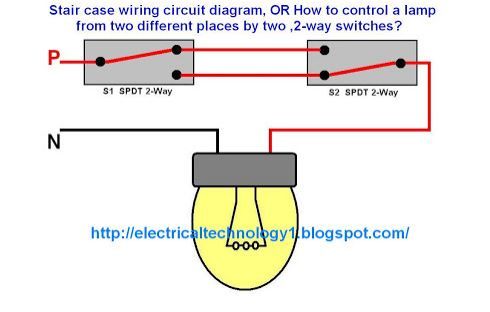
Ive been working on wiring schematics for my truck and I want to follow up on the light circuit with two switches. I drew one the way I understood you to mean by connecting the two switches to the same relay. If the back switch is on and then I get in my truck and notice the light is on, would flipping the switch in the cab turn it off?
I am looking to wire it up like residential stair lights, where you turn on the lights with the lower switch and turn the light off when you get to the top with the other switch. I drew up another scenario with that in mind, will the second setup do what I want? Is it doing the same thing as the first one and I am just overcomplicating it?

 04-23-2014, 07:48 AM
#10
Senior Member
Honestly, if you are new to wiring you don't need to do any wiring at all. I'm on the local fire dept. and just went to a car fire yesterday. The cause was faulty wiring to an aftermarket radio.