
2020 5.0 Platinum - Big 3 and Replacing the Alternator Charging Wire
 01-28-2021, 11:36 PM
#1

So this is more of an information thread at this point than anything as I am trying to hash this out before building cables and diving in. Moreover I am looking to see if anyone knows different or if I have just missed something.
I have a '20 5.0 and for my own reasons want to do the Big 3 (replace the grounds) as well as upgrade the alternator to the battery wire...at least this is what I thought I was going to do. It now appears it might be considered a Big 5?
Some back ground on me is I completely upgraded the charging systems on my '93 Coupe and '83 T-bird with the 3G conversions (130A alternator) and ran a 4 ga wire with a 150A fuse to the inner fender mounted starter solenoid then from the same side of the starter solenoid to the battery (+). Also upgraded other (+) cables and reworked the batt (-) to K-member, k-member to block, and block to the firewall. This corrected all the issues with adding the MDS boxes, stereo gear, better lighting, Mark VII electric cooling fans, mini starters (OEM worm gear starter), etc. to systems that were once charged by a 60A alternator. I have done this mod on several other Fox body cars and replaced cables on several SN95 and S197 Mustangs for friends.
So I found out that the alternator on the 2020 5.0 Platinum is a 240A unit and how the BMS controls the alternator charges the battery is different than how it worked on my '14 Limited.
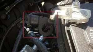
The '20 no longer has the hall affect sensor around the negative leads from the battery to ground like my '14. This is the hall effect sensor that was on my '14:
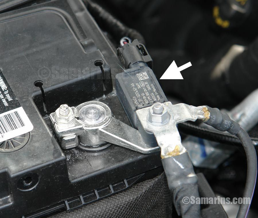
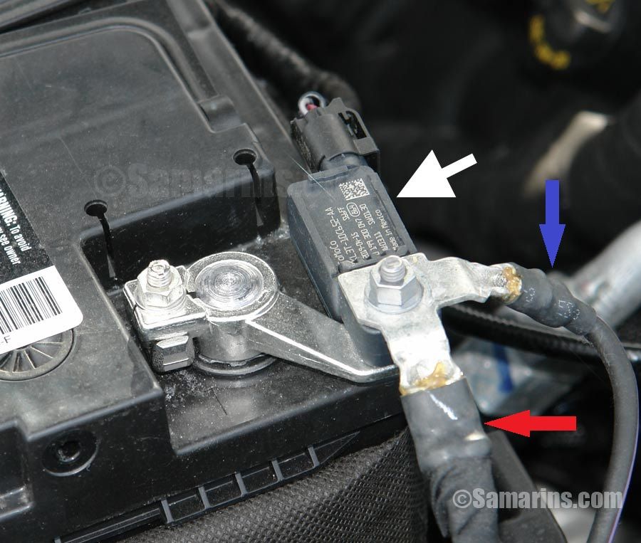
This new system uses a shunt based sensor that mounts directly on the negative terminal of the battery and all the ground wires connect to it. You can see it on the negative terminal as there are a couple of wires going to the sensor itself. This seems to hold true for the '18-'20 trucks as the '15-'17 trucks still have a hall effect sensor. This is a stock picture that shows the shunt sensor really well:
Another difference is where the power cable from the alternator charging post goes. On my '14 the alternator charge wire went to what Ford calls a circuit breaker (actually a distribution blcok with two fuses - 250A & 125A) that was attached to the battery (+) terminal.
.jpg?width=1920&height=1080&fit=bounds)
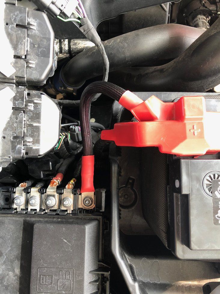
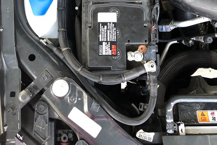
My '20 did not have this and I could not believe Ford was not using a fuse so a lot of digging around on the interweb (sorry old GMG reference). On the '20 the alternator charge wire now goes to the high current battery junction box (HCBJB) which is between the battery and the firewall on my truck. There is a strip of high current fuses on the engine side of the HCBJB and the alternator charge wire attaches to a 300A fuse. As far as I can tell this holds true for the '15-'20 trucks. This picture is off of my truck and it shows the HCBJB connections really well. The stock power wire attached from the battery is the post closest to the battery and it appears to be maybe an 8 ga. wire at most. The wire coming from the alternator attached to the middle post and it is a 4 ga. at most.
Here you can really see the alternator wire attached to the middle post of the HCBJB and the battery to the HCBJB replaced with a 1/0 cable (this is a picture the dhmcfadin posted):
With all of this it looks like that if you want to do the Big 4 its actually a Big 5 on the newer trucks. This would be the following:
Battery (-) to chassis - easily seen in front of the battery attached to the core support.
Battery (-) to engine block - have heard this runs down to a bolt or stud on the starter, will have to confirm
Chassis to cab - factory wire is from the frame to the cab under the passenger front foot well.
Battery (+) to the post on the HCBJB
300A fuse on the HCBJB to the post on the alternator
I plan on running 1/0 on all of this. Some may say this is not necessary as they have all kinds of stuff loading the factory wiring and so far so good but I like a little bit of overkill on stuff like this.
I am working on seeing if I can just leave the BMS alone and not disable it. Sent a PM to stormsearch as he seems super knowledgible about this whole system. Hopefully I get a response from him and can update this thread with that information.
That is it for now.
I have a '20 5.0 and for my own reasons want to do the Big 3 (replace the grounds) as well as upgrade the alternator to the battery wire...at least this is what I thought I was going to do. It now appears it might be considered a Big 5?
Some back ground on me is I completely upgraded the charging systems on my '93 Coupe and '83 T-bird with the 3G conversions (130A alternator) and ran a 4 ga wire with a 150A fuse to the inner fender mounted starter solenoid then from the same side of the starter solenoid to the battery (+). Also upgraded other (+) cables and reworked the batt (-) to K-member, k-member to block, and block to the firewall. This corrected all the issues with adding the MDS boxes, stereo gear, better lighting, Mark VII electric cooling fans, mini starters (OEM worm gear starter), etc. to systems that were once charged by a 60A alternator. I have done this mod on several other Fox body cars and replaced cables on several SN95 and S197 Mustangs for friends.
So I found out that the alternator on the 2020 5.0 Platinum is a 240A unit and how the BMS controls the alternator charges the battery is different than how it worked on my '14 Limited.
The '20 no longer has the hall affect sensor around the negative leads from the battery to ground like my '14. This is the hall effect sensor that was on my '14:
This new system uses a shunt based sensor that mounts directly on the negative terminal of the battery and all the ground wires connect to it. You can see it on the negative terminal as there are a couple of wires going to the sensor itself. This seems to hold true for the '18-'20 trucks as the '15-'17 trucks still have a hall effect sensor. This is a stock picture that shows the shunt sensor really well:
Another difference is where the power cable from the alternator charging post goes. On my '14 the alternator charge wire went to what Ford calls a circuit breaker (actually a distribution blcok with two fuses - 250A & 125A) that was attached to the battery (+) terminal.
My '20 did not have this and I could not believe Ford was not using a fuse so a lot of digging around on the interweb (sorry old GMG reference). On the '20 the alternator charge wire now goes to the high current battery junction box (HCBJB) which is between the battery and the firewall on my truck. There is a strip of high current fuses on the engine side of the HCBJB and the alternator charge wire attaches to a 300A fuse. As far as I can tell this holds true for the '15-'20 trucks. This picture is off of my truck and it shows the HCBJB connections really well. The stock power wire attached from the battery is the post closest to the battery and it appears to be maybe an 8 ga. wire at most. The wire coming from the alternator attached to the middle post and it is a 4 ga. at most.
Here you can really see the alternator wire attached to the middle post of the HCBJB and the battery to the HCBJB replaced with a 1/0 cable (this is a picture the dhmcfadin posted):
With all of this it looks like that if you want to do the Big 4 its actually a Big 5 on the newer trucks. This would be the following:
Battery (-) to chassis - easily seen in front of the battery attached to the core support.
Battery (-) to engine block - have heard this runs down to a bolt or stud on the starter, will have to confirm
Chassis to cab - factory wire is from the frame to the cab under the passenger front foot well.
Battery (+) to the post on the HCBJB
300A fuse on the HCBJB to the post on the alternator
I plan on running 1/0 on all of this. Some may say this is not necessary as they have all kinds of stuff loading the factory wiring and so far so good but I like a little bit of overkill on stuff like this.
I am working on seeing if I can just leave the BMS alone and not disable it. Sent a PM to stormsearch as he seems super knowledgible about this whole system. Hopefully I get a response from him and can update this thread with that information.
That is it for now.
Last edited by Aerocoupe; 01-30-2021 at 04:45 PM. Reason: Swapped some pictures around

The following 3 users liked this post by Aerocoupe:
01-30-2021, 09:21 AM
#2
stormsearch got back to me and by putting all the grounds on the stud side of the shunt sensor the BMS will function normally. Was going to look into the battery to block ground today but as luck would have it it’s raining. That also kills my plans to look at the complexity of changing out the HCBJB to alternator wire. Hopefully the rain stops here soon and I can check then.
The following users liked this post:
stormsearch (01-30-2021)
01-30-2021, 05:02 PM
#3
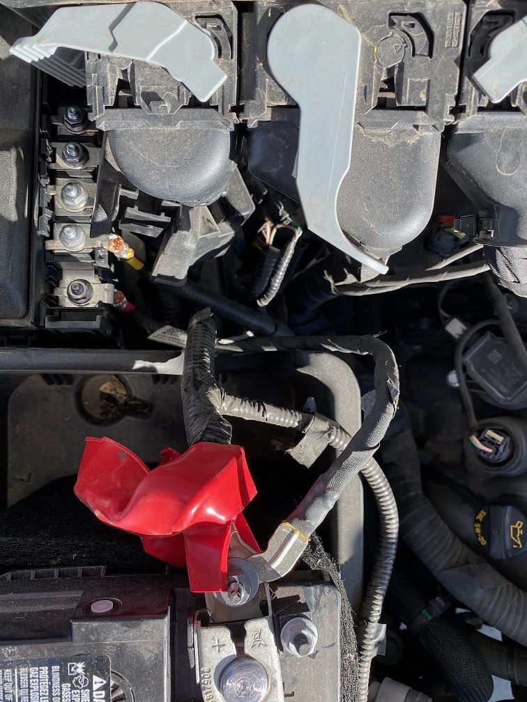
Rain finally subsided and sun came out so I was able to look around on the truck at the ground wires. Interesting note is stormsearch stressed not replacing the ground wire from the battery to the starter. From his past posts you can gather that he works for Ford and knows this stuff very well. He said the starter positive cable and ground cable are specifically sized and they should under no circumstances be altered. I was able to confirm that the ground wire to the starter in fact does exist but there is also another ground wire that runs over to the frame and is attached in plain sight within the passenger front wheel well towards the front. The starter ground wire and the frame ground wire are both in one crimp at the battery and I drew a red arrow to that in the picture below. The battery ground to the body is the blue arrow in the picture.
I think I am just going to disconnect the frame ground wire at the frame and tie it back and just run a new 1/0 ga. from the battery to the frame ground as I really do not want to cut that connection apart. I will trim the battery to body ground "tab" off like dhmcfadin did and run a 1/0 ga. battery to body ground. It looks like the stud on the shunt sensor can be removed so I am going to look into that and see if I can put a longer one in there as adding the three 1/0 terminals (two for the stock wire replacements and one for the stereo ground) to that post will put the nut just barely engaging. You can see this in another picture that dhmcfadin posted:
I also checked out how the power wire from the HCBJB over to the alternator is run and that will be easy to replace as well. May be an experience pulling the alternator but nothing is easy on these new vehicles anymore.
01-31-2021, 06:19 PM
#4
Wether you agree or disagree, I can tell you from 3 years of running my system very hard, the big three is in no way necessary. Upgrade your main power and ground and ground your amps back to the battery.
The following users liked this post:
FrdCrzy18 (03-03-2022)
 02-01-2021, 02:23 PM
#6
Good discussion here:
https://www.f150forum.com/f75/how-big-3-upgrade-46822/
Basically replacing the undersized factory wires dealing with the battery and alternator to take full advantage of the power in the battery and power the alternator is capable of producing.
https://www.f150forum.com/f75/how-big-3-upgrade-46822/
Basically replacing the undersized factory wires dealing with the battery and alternator to take full advantage of the power in the battery and power the alternator is capable of producing.
02-01-2021, 05:04 PM
#7


The factory setup is good for 3456 watts of power as is just saying.
__________________
PM me for special pricing as our contracts do not allow for posting prices publicly.
Serving the forum for over 8 years
Brands we sell include: Kicker, NavTV, PAC, CARiD, Dayton, Second Skin, Audio Control, Skar Audio, JL Audio, Focal and more.PM me for special pricing as our contracts do not allow for posting prices publicly.
Trending Topics
02-02-2021, 01:29 AM
#9
240 amps x 14.4 volts = 3456 watts
__________________
PM me for special pricing as our contracts do not allow for posting prices publicly.
Serving the forum for over 8 years
Brands we sell include: Kicker, NavTV, PAC, CARiD, Dayton, Second Skin, Audio Control, Skar Audio, JL Audio, Focal and more.PM me for special pricing as our contracts do not allow for posting prices publicly.
02-02-2021, 09:25 AM
#10
Agreed and now I feel dumb for forgetting a high school physics equation. I thought you had done some high test testing and would have some graphs and charts but nope just good old math...damnit.
I agree that 3,456 watts is the maximum amount of power available on paper but what about amplifier efficiency and an average of 13.8V? An average Class D is going to be real world 70% efficient at peak and an average A/B will be real world 50% efficient at peak. Take out the power the truck needs to operate and what do we really have left for the stereo? If someone knows what the maximum draw these trucks have on the electrical system it would be nice to know.
I agree that 3,456 watts is the maximum amount of power available on paper but what about amplifier efficiency and an average of 13.8V? An average Class D is going to be real world 70% efficient at peak and an average A/B will be real world 50% efficient at peak. Take out the power the truck needs to operate and what do we really have left for the stereo? If someone knows what the maximum draw these trucks have on the electrical system it would be nice to know.
Last edited by Aerocoupe; 02-02-2021 at 10:08 AM.