When you click on links to various merchants on this site and make a purchase, this can result in this site earning a commission. Affiliate programs and affiliations include, but are not limited to, the eBay Partner Network.
A while back on the "power Folding Mirrors add-on" thread, I have a question, regarding the relay setup: what if I set it up this way, would it work ? Attachment 89465
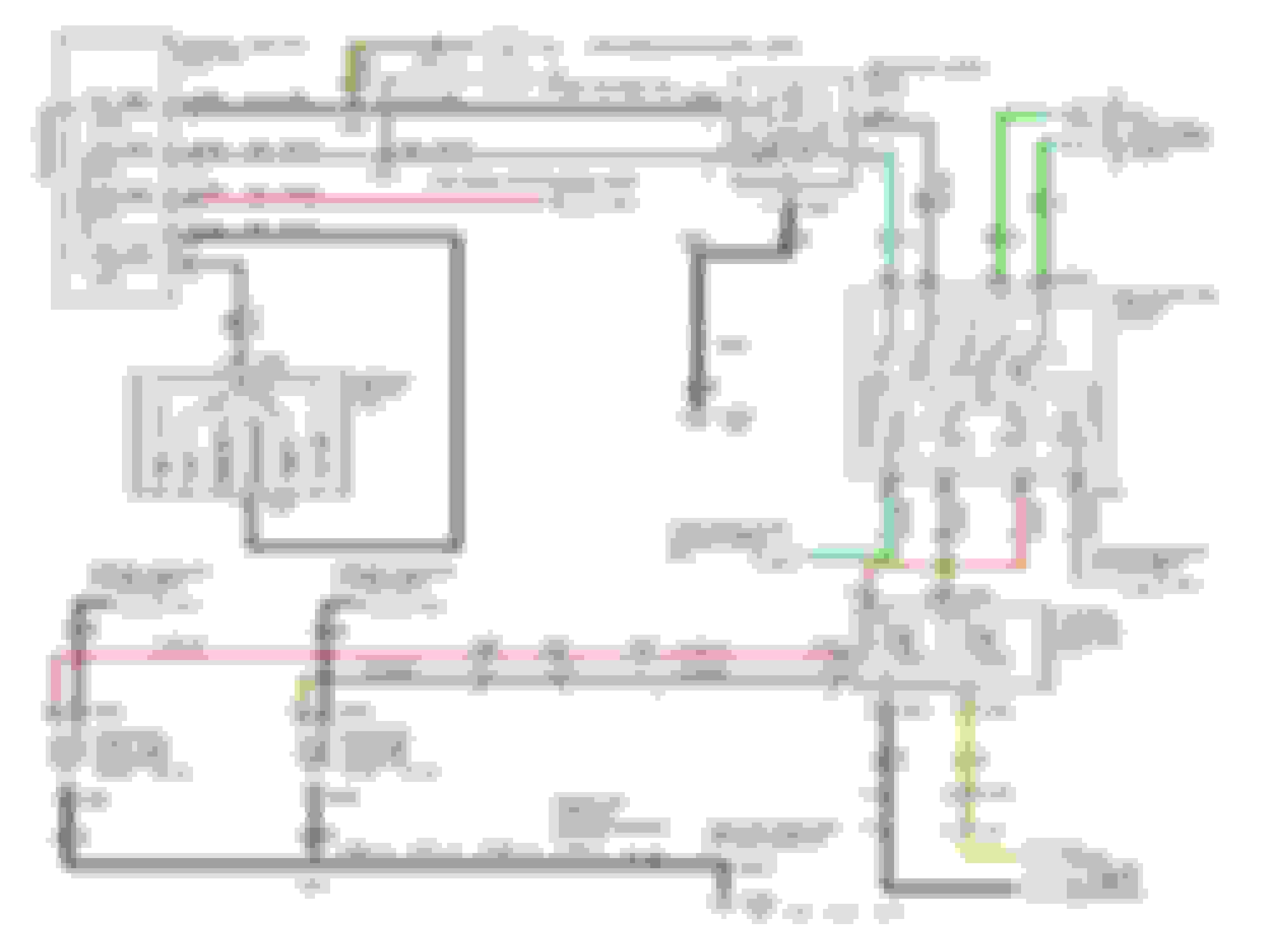
And take a look at the Electrical diagram from the factory, It lookslike they're only using one relay Attachment 89468
Give me some feedback !
TXFRDowner,
Your schematic with one relay will not work because the switch doesn't connect to the coil of the relay. You have the power of the circuit going straight to the switch through the normally closed contact.
Also if you look at the Ford OEM schematic at the Power Fold Module the are two relays. They are just running both mirror fold motors at the same time.
You need two relays for a simple motor direction circuit to work.
Relays are cheap and readily available.
Hope this helps.
I'm really ignorant to relays and circuitry. So in the nutshell the OEM Mirror Power Fold Module is the equivalent of the 2 regular universal 5-pin Relays ?
So If I wanted to go with the Factory (PowerFold) switch, I'd have to get the Factory Relay (8C3Z-14N089-A) in order for it to work, right ?
I'm really ignorant to relays and circuitry. So in the nutshell the OEM Mirror Power Fold Module is the equivalent of the 2 regular universal 5-pin Relays ?
So If I wanted to go with the Factory (PowerFold) switch, I'd have to get the Factory Relay (8C3Z-14N089-A) in order for it to work, right ?
Yes the Power Fold Module is nothing but two relays. Therefore you can buy two standard automotive relays and wire them up the same for much cheaper.
No, you don't have to buy the factory relay if you want to use the factory switch. As long as the factory switch outputs 12V when you want to fold then it will work. That saying you use the schematic that I provided earlier in this forum.
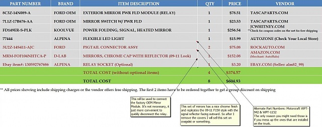
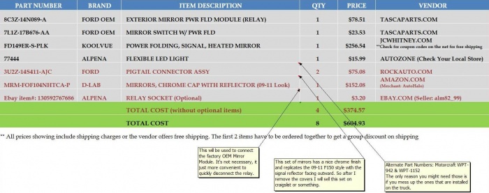
I've been reading about this mod all over the net and thought maybe others might wanna do this too. So I put together this list with some more affordable options.
Here's a list with part numbers and vendors I could find on the net. If you know somewhere we can get these items cheaper by all means share the intel.
The Power Folding Mirrors are not factory. They're made by KoolVue and are an exact replica for a 3rd of the cost.
The LED light strip, I'm just gonna use that to insert inside the amber reflectors and splice it to the existing signal wiring.
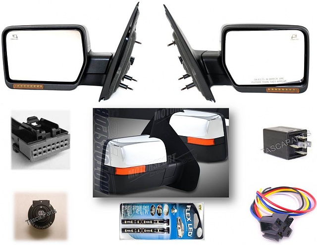
And here's the visual for what these items should look like.
PM me if you want the Excel sheet.
Last edited by TXFRDOwner; 03-07-2012 at 04:23 PM.
This is a Power Fold Mirror Electrical Diagram from Ford that I modified. I added this module to the diagram, it automatically fold/unfold the mirrors on Acc on/off.
Part Number: ZMC-UV1. It's made in Korea. They sell it on ebay just search for "ZMC auto fold module".
I haven't done this to my truck yet but when I do I will post pictures.
Hello, I know this is an old thread but....I have a 2007 supercharged Harley f-150 and the only option it does not have is power fold side mirrors! I would like to do this mod using the factory switches. If you could send me all your directions and schematics for this mod...it would really help me a lot!!! Thanks
Dredging up an oldie, but thought I would document my install for any other XLT owners who tackle this.
First, TXFRDOwner was, by far, the best resource I had for this project.
I bought both mirrors and the Dorman switch from an ebay seller for $300 shipped. The mirrors are power fold/heat/puddle/turn with no memory function.
I HIGHLY recommend buying the pigtail connectors for the switch and mirror connector.WPT998 and WPT1152 are needed. You'll also need a release tool.
These allow you to use the connectors with factory terminals. If you have access to the Ford terminals, use those.
The factory relay is a must, for ease-of-install.
Also handy (for me) was a spool of 18awg 5-wire.
XLT trucks will not have any of the required wires pre-run. You'll need to run 5 wires through the boot on the drivers side, and 4 on the passenger side. Also, you'll need to make a ground in each door at pin 8 on the mirror harness. I used one of the mounting bolts as a ground.
The puddle lights in these aftermarket mirrors are 194 bulbs, and they pop out easily -- so you can put LED lights in those very easily.
Tapping the illumination wire is already documented in the How To section, use that.
I'll put some pictures up on tapping the turn signals later.
I mounted the relay/controller module next to the fuse block, passenger kick panel. It made more sense to me, since I had to pick up power there anyhow, and a good ground is easily accessible. There is enough wiring in the drivers kickpanel area already, plus you're tapping illumination and signals over there.
Whole project should run you about $500 or less. The pigtail harnesses are spendy, so if you can source the terminals and crimp them down yourself, you can save $60 easily. I also bought a new spool of 5-wire, so if you have that already there's $20 off too.
Tracing the turn signal wires. if they're not conveniently already in the mirror connectors in pin# 10 , you have to go get them from under the steering column. T-tap connectors are your best friends.
I could be wrong but based on the diagram I see that the two turn signal wires (OG-LB & LG-OG) are going to the rear lamps from the Junction Box 11-1 ... Those two could possibly be running in that bundle of wires in the door sill. Big possibility. Worth checking
For the record, the OG/LB & LG/OG wires are in the drivers side wiring channel. Unfortunately, they carry the brake signal as well as turn signals. Looks like the only place that's reasonable to grab them is under the column. PosiTap connectors up there and we're in business.
For the record, the OG/LB & LG/OG wires are in the drivers side wiring channel. Unfortunately, they carry the brake signal as well as turn signals. Looks like the only place that's reasonable to grab them is under the column. PosiTap connectors up there and we're in business.
LG/WH and WH/LB are the wires to grab for signal.
Oh yeah, Didn't notice that. Good catch, I'm glad you figured that out. That's good information another forum member can use.
Last edited by TXFRDOwner; 01-17-2016 at 05:57 PM.

 03-05-2012, 12:43 PM