When you click on links to various merchants on this site and make a purchase, this can result in this site earning a commission. Affiliate programs and affiliations include, but are not limited to, the eBay Partner Network.
Thanks @pontisteve. After almost 2 years, I had about given up on anyone going out on a limb and taking a good ole college try at this question.
Although the specific answer to the question (WHAT, IF ANY, is the base, static,º Advance without any requested retard) is still OPEN & UNKNOWN, I have learned a lot about subject. I have done a complete timing job on my '04, found the OBDII PIDs for Bank 2 VCT Solenoid duty cycle (VCT2DC - 091E) and Bank 2 cam position error (VCT2ERR - 091D), and I have got my Torque Pro formulas and gauges working nicely. It provides a valuable visual diagnostic of Phaser and VCT operation. I posted all the PIDs and formulas for Torque Pro in 'The Final Repair Guide thread in this post: https://www.f150forum.com/f4/final-r...4/#post5133357
Although the above Torque routines / gauges do not accommodate ANY advance (if such really exists), I NOW believe the unique design of the 'OEM PHASER' allows the PCM to apply a very slight amount of actual 'advance' (Understanding that - to avoid valve/piston contact, it cannot be very much). The design of combustion chamber can, at some slight loss of compression ratio, be made to accommodate a few degrees of valve advance. I note that the spring loaded locking pin in the Phaser locks the Phaser gear to the camshaft -- just slightly shy of the chamber's advance end. (See 1st photo) NOTE the small milling in the edge of two of the Phaser chambers. They equalize hydraulic pressure in the advance/retard chambers - 'increasing the amount of oil pressure necessary to move the cam further toward advance end. THIS CONDITION is met when engine RPM rises and OIL PRESSURE rises very quickly above the point necessary to release the spring loaded locking pin. If NO duty cycle is being applied to VCT Solenoids, all oil pressure is still being routed into the ADVANCE CHAMBERS, releasing the locking pin and moving the vanes all the way forward against the chamber end - slightly advanced (perhaps 4-5º, ?????). At idle, oil pressure is below the spring force and the Phaser locking pin captures and locks the Phaser at 'around' zero degrees. ///when this pin wears and gets sloppy - you get the infamous diesel sound ///.
BTW. Is the PCM 4 digit code and 7 digit strategy code available from OBDII? Could that be one of the ones I can't figure out WTH they are?
Thanks again for responding.
These small millings in the edge of chambers equalize pressure on both sides of the vane 'just before' the vane reaches the end. Slightly toward advance from the position shown, the spring loaded pin snaps into place locking inner / outer parts of phaser together.
Note millings in edges of chambers at 2 o'clock and 7 o'clock. In this photo, vanes are positioned at full advance (whatever camshaft degrees that would be.... ???) It amazes me that Livernois cannot answer that question since that is the position they 'lock' cams in.
The PCM code is the 4 digit code on the sticker located on the PCM itself. It might look like ABC1 or something similar. This is the tear tag, or catch code of the PCM, and represents what tune came in that computer from the factory.
The 7 digit strategy code is a slightly more advanced version of the same thing, and it indicates what tune is in the computer NOW. Remember, Ford makes updates as they learn about their mistakes. So an ABC1 tune can become an ABC2 with an update. The computer sticker stills says ABC1, but the strategy changes inside the computer. A strategy code might look like FBGI0A1A, where usually the first 5 digits are the PCM strategy family, and the last 3 digits indicate the particular tune.
The catch code is visible in large letters on the PCM sticker. The strategy code is accessible with most scan tools, when you read factory information like VIN code, etc. They might call it something else, like software code or revision or something like that. If you have an SCT Xcal device, it calls it a strategy code.
The space you refer to "before the locking pin" may not be designed for advancing the cam, but rather it just gives the phaser enough room to actually stick the pin in. Sometimes things need slightly more room than they actually require, just to ensure they don't hit a brick wall .00001" away from where they need to be. So it could just be a little overshoot room, not intended to actually advance the cam.
Looking closer at a cam gear picture, it appears there are 42 teeth. Divided equally among 5 divisions, there are 8.57 degrees per tooth and 72 degrees per division, not all of which are actually usable since there are dividers. Each division would represent 8.4 teeth.
Poking thru some 4.6 3v Mustang tunes, it appears that the max number of degrees of cam advance I see is 60 degrees. Times 5 that would be 300 degrees, leaving 60 degrees left. That remaining 60 degrees would be the equivalent of 7 teeth total, or approximately 1.4 teeth per division of "unusable space".
In the calibration, the cam is at 0 degrees of retard at idle, and between 20 and 60% load it's at it's highest retard. Max retard of 60 degrees is only commanded at 4500 RPM and 30% load. This light/medium load retard is used to create internal EGR flow thru valve overlap. Essentially, it replaced the EGR valve.
The VCT function is also used at higher RPM and high load, to retard the cam around 9 degrees at WOT for performance benefits. It commands 2.5 degrees at 4500 RPM, and 9 degrees by 5750 RPM and up. Your truck may be different in it's calibration, but overall it is going to meet a similar goal.
I'm guessing the 60 degree retard limit is the physical limitation of the cam phasers due to the 5 dividing walls, and is probably the same thru various models.
FYI, I have turned off VCT for customers before. Some guys will spend the big bucks to fix those cam phasers once, but the second time around they are not so willing to spend the money and are just mad they failed again. It works perfectly fine to replace the cam phasers with regular non-VCT cam gears and then turn off VCT in the tune. Those same customers reported no difference in mileage or power, which kind of surprised me.
You may find some helpful datalogging by using an SCT X3 and Livelink 6.5 or Livelink II software. The software is a free download, and you can pick up a VIN-locked used X3 for probably $50.
WOW! If I could have "Thanked" you multiple times I would have done so. Exactly the kind of authoritative information I have been seeking.
Originally Posted by pontisteve
...
The space you refer to "before the locking pin" may not be designed for advancing the cam, but rather it just gives the phaser enough room to actually stick the pin in. Sometimes things need slightly more room than they actually require, just to ensure they don't hit a brick wall .00001" away from where they need to be. So it could just be a little overshoot room, not intended to actually advance the cam.
Makes perfect sense, and although it shoots down my 'lay' assessment of some design for slight advance. It always seemed a little bit flaky design idea.
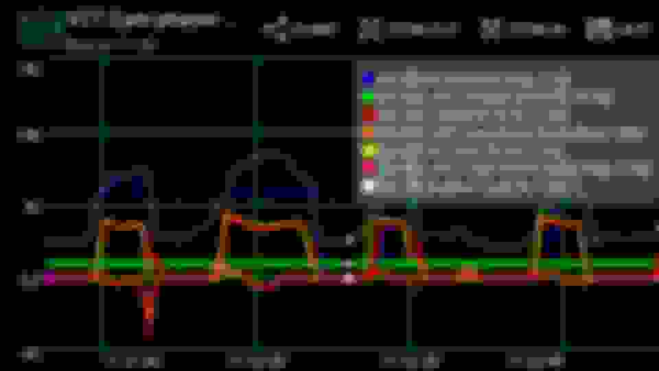
Your numbers confirm operation I have observed with my Torque Pro logs & graphs below. My formula produces 62-63º [[Crankshaft Degrees]] of 'maximum retard'. I will be revisiting my math against all your calculations - as basically I fine-tuned mine after my new Phaser job. The more important thing to me was the zero degrees CAMERR & VCT2ERR - which I found to be very stable at zero - except when requested retard (RCAM) changes quickly. This can clearly be seen in the graph at 11:31:49 (pink & Org trace), and the graph otherwise tracks your Mustang tune numbers. They also confirm what I have told many (as seen in the graph) that the PCM employs some degree of retard under a majority of engine operating conditions.
Thanks again and BTW - Welcome to the Forum. From what I have read in your four posts so far, I hope to be seeing a lot more from you.
Graph is generated with "Real Time Charts for Torque Pro", a very powerful, intuitive and flexible graphing Plug-In for Torque Pro.
Last edited by F150Torqued; Mar 28, 2017 at 09:19 PM.
Reason: Clarify "Crankshaft Degrees" & Credits to graphing app.
I can't say that my math is a fact. I'm just doing a little calculating, looking at the pics of a cam gear, and counting teeth. But it does seem to line up pretty good with the real facts that 60 degrees appears to be max advance in the tune.
Then again, try to remember that the tune just commands a retard degree number, then applies a duty cycle to the phaser. It doesn't mean that's the number it actually got. However, that's what the closed loop system is for. If the cam angle error is not 0, then small corrections are made to the VCT duty cycle until the error is 0.
There are different rates at which the computer commands results too. The computer makes big jumps when it needs to, and fine adjustments when it's getting close.
If you get me your 4 digit PCM code or 7 digit strategy code, I can show you some of the tables for your trucks tune.
FYI, all I see is a little green box when you post logs or pictures.
FYI, all I see is a little green box when you post logs or pictures.
Bummer! I was hoping for comments (or affirmation of my optimistic lay opinion) of the 'post timing job' operation represented by the graphs being normal.
From your FYI, it sounds like you were able to view my uploaded Phaser gear photos (they are .JPG files) while the graph is a '.PNG' file. A friend checked for me and reports both come up for him in Explorer and on mobile as they do for me.
Possibly your browser doesn't have the file association established for .PNG ????
Not trying to be a smartass. But at least that's easy to check. From your desktop, >Start >Default Programs > Associate a file type or protocol with a specific program. Scroll down and note the default program for .jpg file type, and copy that default down to .png (or enter whatever other photo program is desired for processing photos.
I posted a separate thread but want to ask here since there are some knowledgeable people posting:
https://www.f150forum.com/f12/5-4l-3v-p0011-p0021-fresh-rebuild-412428/
My phasers are not retarding at all even though %DC to the solenoids is going up to 91% . The entire timing drive is new OEM ford parts, motor was rebuilt 2k miles ago. It does have low oil pressure @ idle (12 psi) but wouldnt there be enough pressure at higher RPMs to unlock the phasers and retard the cams? Gonna check the solenoids first but any other thoughts? My plan is to go with high volume oil pump and get the cast iron tensioners to replace the 10340 pump and OEM plastic tensioners but I'm all ears for other troubleshooting ideas.
here are the data logs, idk why the RCAM and RCAM2 are not moving but it seems it is requesting retard since the CAMERR and %DC goes up then flips the enable bit eventually to shut down VCT and set the MIL light with P0011 and P0021
Wow. That's weird. You sure you didn't install lockouts in those phasers! I agree completely with your diagnostic assessment of the data stream. The graphs indicate CAM ERROR 1 & 2 ('+' = Over Advanced) just track the solenoid duty cycle signal being applied to the VCT solenoids. When retard is requested - cams just don't budge. And I agree that oil pressure above ~ 800 (where PCM begins requesting retard) your oil pressure is probably already up to 40 - 45 lbs and should be plenty sufficient to retard cams. Clearly - that is not happening.
Check simple things 1st. Realize the signals we are looking at from OBDII are 'digital' numeric outputs from the PCM --- NOT a volt meter connected to the VCT SOLENOIDS.
Make sure you have +12 Volts source voltage on pin 1 of the VCT Solenoids. Verify they are plugged in good, good connection back to the PCM. You 'CAN' actually stick a pin through the PCM signal wire (pin 2) which runs back to the PCM pins 67 & 68 (bank 1 & 2 respectively), and attach a jumper wire to the pin through a 50 ohm resistor. Ground a steel file to the engine or frame ground and drag the resister up and down the 'file' to produce duty cycles to the solenoid. This will not harm the PCM. The PCM signal to the VCT is passive, pulling it to ground with duty cycle pulses when retard is called for. This will actuate (open) a properly operating VCT solenoid. If the 'locking pin' in the phaser is locked @12 lbs oil pressure - NOTHING will happen. If not it will retard the cam on that bank and cause very rough idle. When you stop actuating the solenoid, you may have to rev the engine to build oil pressure up enough to push the cam back to advance / locked position. If smooth idle returns - it's a good thing. It means your oil pressure is adequate to push cams back to full advance position without any acceleration help.
I do have a question about your data stream. Are you on latest version of Torque pro? I know the PCM will NOT request retard < 25 % engine load. I believe the PCM 'IS" issuing VCT duty cycle signals to both solenoids (or there should be NO VCT DC requests). The ONLY thing that makes sense about RCAM and RCAM2 staying flat-lined around zero on your graph would be a problem in the formula in Torque.
From the 'Manage Extra Sensors / PIDs' screen for RCAM or RCAM2, you can press the TEST button and see each step of the formula being executed. Check that and make sure it is 'ABS(SIGNED(A)*256+B)/12.8' I think you have a failure in that formula in Torque Pro.
Post back and fill us in on your progress / findings.
Thanks for the suggestions. I'll hook up an oscilloscope to the pins and/or plug in an old solenoid I have to test it. If the solenoid valve is in fact moving it seems to me it has to be an issue with the phaser itself, lock pin stuck or something. Is there a way to check phaser operation without removing them?
The only way I know of is through Torque Pro - or some other OBDII diagnostic facility that gives readings from the relevant sensors.
I can tell you based on my 2004 5.4 that I can place tranny in '2nd' gear selection position, with brakes applied and torque the engine above 800 rpm and the PCM will attempt to apply retard. Mine works real smooth and I can 'feather' the accelerator and just about establish any degree retard I want with this method. When I idle back down, all retard is removed as RCAM returns to zero and cam error stays at (or may bobble briefly) around ZERO the entire time. Trusting the OBDII signals - says that shows they are working.
Let's concentrate on getting your Torque Pro formulas correctly reporting RCAM and RCAM2. (Is your Torque Pro a paid version from Google Play? or a knock off shipped with a dongle?).


 If I could have "Thanked" you multiple times I would have done so. Exactly the kind of authoritative information I have been seeking.