When you click on links to various merchants on this site and make a purchase, this can result in this site earning a commission. Affiliate programs and affiliations include, but are not limited to, the eBay Partner Network.
This is a how-to guide on the install of the factory intrusion sensor on a 2015+ F150. The credit for this conversion goes to @2016BoostedGreyGoose, He did the legwork - I’m just the documenter of this security upgrade.
I would also like to recognize the FORScan guru – @Livnitup, @Ryan B – Who’s thread I pulled terminal part #’s from, & @flsdiver, Who I borrowed a BCM photo from.
For this and any other modifications requiring work on your trucks electrical system, disable the Battery before starting any work to the vehicle.
Your vehicle must be equipped with Ford’s Perimeter Alarm system currently for the intrusion sensors to work.
Disclaimer: You are doing this installation at your own risk - BGG, myself, as well as any other contributor to this guide will not be responsible for any damages that may occur to your vehicle while attempting this modification. We strongly advise obtaining a service manual; it will prove to be a useful tool for information regarding your particular truck.
Parts Required:
• Overhead console with Intrusion Sensors (Part # varies according to your options, trim color, etc.)
• For connector C2280C - Pigtail Kit # DU2Z-14474-DA or if you prefer to make your own connections, Molex MX-150 Part #: 3044983
• For connector C2280E - Pigtail Kit # DU2Z-14474-AA or if you prefer to make your own connections, TE Connectivity terminals Part #: 1924955-3
• TE Connectivity connector Part #: 1241634-1, (Sensor connector plug) One connector needed
• TE Connectivity Terminal Part # TE-928999-1(Female Terminals for above listed connector) Three terminals needed
• 22 ga. Wire
Intrusion Sensor Part numbers - There have been some members attempt this mod only to find they cannot clear the DTCs to complete configuration of the sensors. These sensor part #'s may prove helpful in getting the correct sensor for your particular vehicle.
(Thanks to Livnitup for sharing the following information )
For vehicles manufactured 10/20/2014 to 8/01/2015 - use part # FL3Z-15K609-A
For vehicles manufactured 8/01/2015 to 10/09/2016 - use part# FL3Z-15K609-B **NOTE: The "B" sensor was listed as a replacement for the "A" version, Now there is a "C" version that replaces the "B" **
For vehicles manufactured 10/10/2016 to 7/17/2017 - use part# HC3Z-15K609-A
For vehicles manufactured 7/17/2017 and after - use part# HC3Z-15K609-B
*@2016BoostedGreyGoose has purchased the required parts to build ready-to-install harnesses for anyone that would rather not build their own. As you know from his Raptor Wheel harnesses, his work is top notch.
Also, from time to time he may even have consoles available to go with his harnesses….again this is for the ones that would prefer not to have to source parts to make their own.
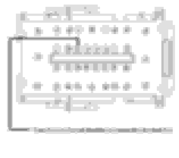
BCM Wiring Locations:
• C2280C – You will need to add a terminal to pin # 15 (Fuse # 11), which will be the power wire for the sensor connector in location # 1
• C2280E – you will need to add a terminal to pin # 36 (LINbus # BCM # 3), this will go to the sensor connector location # 2
• Ground Wire: sensor connector location # 3 is run to a ground location within the truck; I chose a frame bolt near the BCM for this connection.
I chose to run the wires up the A-pillar behind the side airbag, then straight over to the overhead console.
After making the necessary FORScan changes, under the wrench icon run BdyCM Local Interconnect Network New Module Calibration. After successful completion of this, follow up by going to the clipboard icon and running the BdyCM On Demand Self Test. Clear the Diagnostic Trouble Codes (DTCs) and then retrieve the DTCs from the BdyCM to confirm all DTCs have been cleared.
If you have any DTCs in the BdyCM the LINbus configuration will not complete successfully.
.
Last edited by Firerunner; 03-22-2021 at 04:01 PM.
Reason: refined parts list
Been waiting on this. Thank you so much Boosted and Firerunner.
How can I tell if I have the perimeter alarm system already?
The easiest way to tell (other than looking at the window sticker) is to lock you truck with the windows down, then reach in and open the door from the inside.... if you have the perimeter alarm it will set off a warning to start the truck before it sounds the horn.
The easiest way to tell (other than looking at the window sticker) is to lock you truck with the windows down, then reach in and open the door from the inside.... if you have the perimeter alarm it will set off a warning to start the truck before it sounds the horn.
Thank you. I just checked my. Window sticker and I have the perimeter alarm. Whoop! Off to Ebay for some stalking until I find a console.
Any idea if just replacing the roof harness with one from a platinum would work? I�ve already have one but I haven�t attempted it yet as I�m still waiting for other parts to arrive (overhead console and new visors). Otherwise amazing job on the write up.
Fantastic write-up. Thank you for your efforts. How does one go about getting the correct part# for the overhead console based on one�s trim package?
When I get off work this afternoon I'll get you a starting point to use for searching.
Originally Posted by techietruckguy
Any idea if just replacing the roof harness with one from a platinum would work? I�ve already have one but I haven�t attempted it yet as I�m still waiting for other parts to arrive (overhead console and new visors). Otherwise amazing job on the write up.
You can replace the roof harness, but you will still need to run the wires from the BCM down the passenger side wiring channel to where your roof harness connects to the rest of the trucks harness.

 05-20-2018, 09:29 PM