Rigid Industries SR-Q Back-up lights install '09-14
 05-16-2014, 10:44 PM
#1
Member
Thread Starter

Here's my how-to for the Rigid Industries SR-Q Diffused Back-up light kit Part # 98002
DISCLAIMER: I am not an expert, this is just the way I did it and I think it's a good way. Rigid's instructions are actually pretty good and the harness is nicely made so it shouldn't be too difficult.
First of all the instructions. If for SOME reason you don't have the instructions from Rigid, here:
http://i1316.photobucket.com/albums/...psf600cbf7.jpg
&
http://i1316.photobucket.com/albums/...sb0daefa7.jpeg
Now lets begin. First lay out the harness on the ground. Make sure all the wires are good with no nicks or cuts.
Then start on the red wire with the fuse. The eyelet connector goes on the battery's positive (duh).
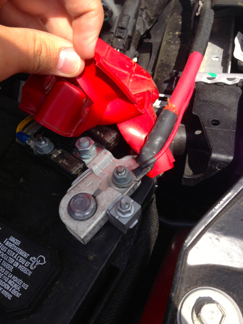
Then feed the wire along the front of the truck slipping it and the fuse under that plastic panel.
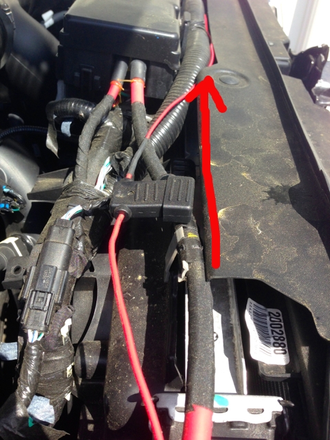
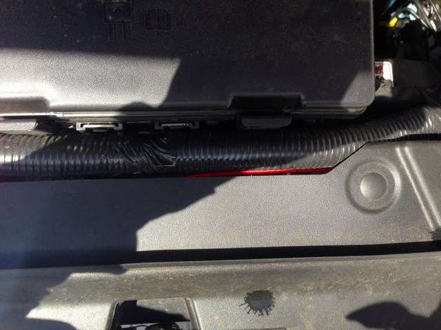
Bring it around the airbox, you can bring it under those bolts but no need.
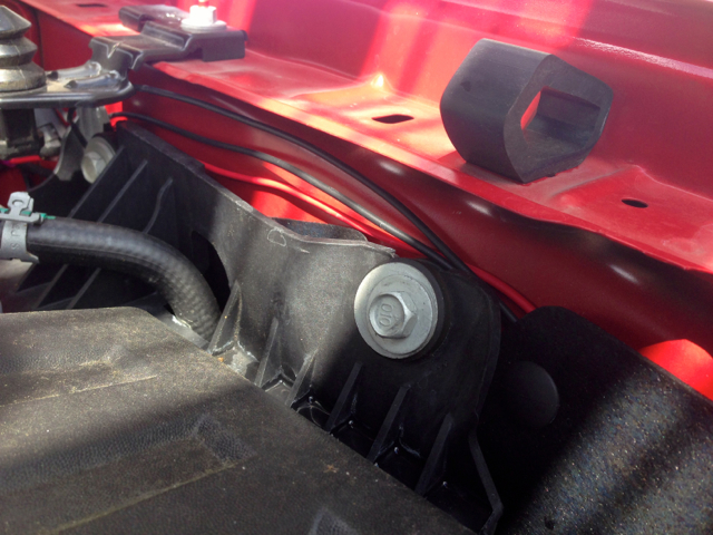
This is where the fun starts. You should have reached the relay by now. The black wire with the eyelet is the ground. Find any spot on the frame to ground it. There's a built in ground on the vertical frame piece beside/behind the intercooler that's really close to where we passed the red wire earlier, but I got lazy and used the firewall.
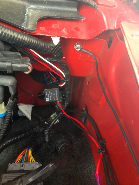
Now it's time to feed the wires into the cab through the firewall. Instructions say to put the relay under the dash, but I couldn't figure out how to get the relay through that grommet so I just put mine in the engine bay.
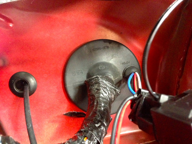
Make a small slit in the small "nipple" of the grommet. Feed the short black, red, and blue wires as well as the long white wire through that "nipple". Try to get the relay as close to that grommet to give you maximum wire length to play with inside the cab.
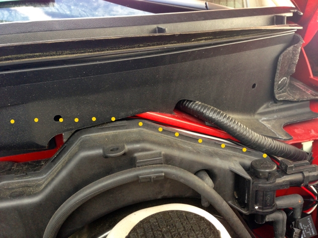
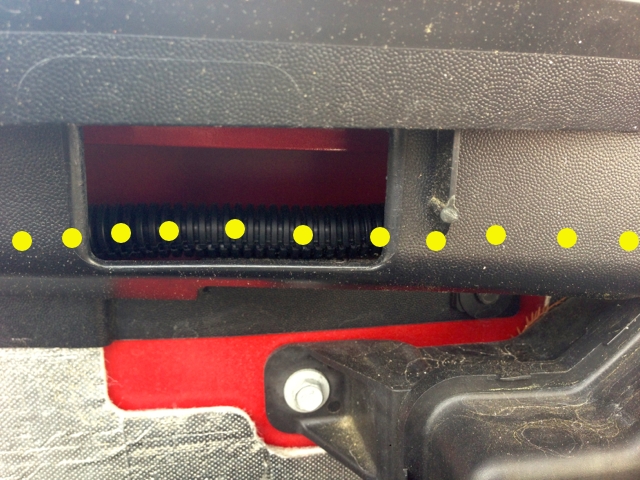
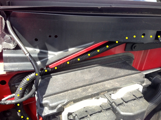
Now, take the long white wire, the two long blacks, and the two long reds. These are all going to the back of the truck. I couldn't find a good place to feed these wires inside of their loom down to the underbelly while on the driver side of the truck. So I brought it across the engine bay through the underside of the wiper cowl. You will need to remove those lower bolts of the cowl to get the wire up in there. I really think it looks nice and factory. Just follow the dots!
To be continued...
DISCLAIMER: I am not an expert, this is just the way I did it and I think it's a good way. Rigid's instructions are actually pretty good and the harness is nicely made so it shouldn't be too difficult.
First of all the instructions. If for SOME reason you don't have the instructions from Rigid, here:
http://i1316.photobucket.com/albums/...psf600cbf7.jpg
&
http://i1316.photobucket.com/albums/...sb0daefa7.jpeg
Now lets begin. First lay out the harness on the ground. Make sure all the wires are good with no nicks or cuts.
Then start on the red wire with the fuse. The eyelet connector goes on the battery's positive (duh).
Then feed the wire along the front of the truck slipping it and the fuse under that plastic panel.
Bring it around the airbox, you can bring it under those bolts but no need.
This is where the fun starts. You should have reached the relay by now. The black wire with the eyelet is the ground. Find any spot on the frame to ground it. There's a built in ground on the vertical frame piece beside/behind the intercooler that's really close to where we passed the red wire earlier, but I got lazy and used the firewall.
Now it's time to feed the wires into the cab through the firewall. Instructions say to put the relay under the dash, but I couldn't figure out how to get the relay through that grommet so I just put mine in the engine bay.
Make a small slit in the small "nipple" of the grommet. Feed the short black, red, and blue wires as well as the long white wire through that "nipple". Try to get the relay as close to that grommet to give you maximum wire length to play with inside the cab.
Now, take the long white wire, the two long blacks, and the two long reds. These are all going to the back of the truck. I couldn't find a good place to feed these wires inside of their loom down to the underbelly while on the driver side of the truck. So I brought it across the engine bay through the underside of the wiper cowl. You will need to remove those lower bolts of the cowl to get the wire up in there. I really think it looks nice and factory. Just follow the dots!
To be continued...
Last edited by goneMINIcrazy; 05-17-2014 at 11:42 AM.
 05-16-2014, 11:02 PM
#2
Member
Thread Starter
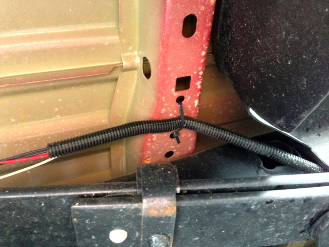
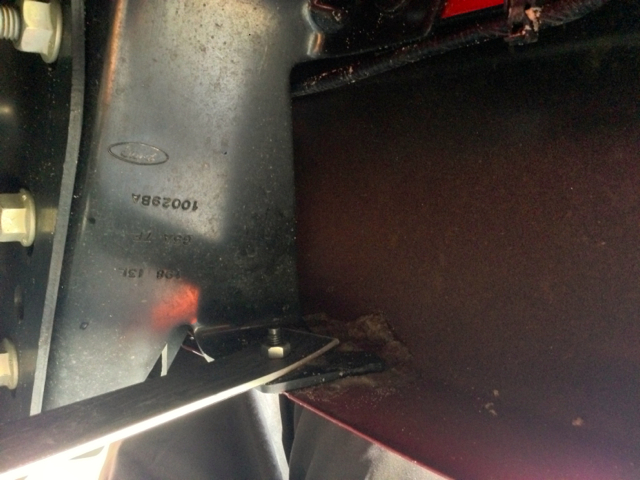
Now you feed it down the passenger firewall.
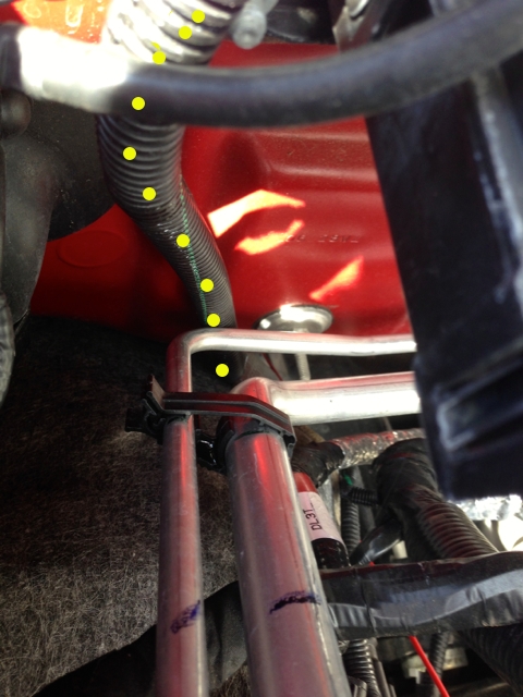
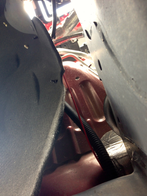
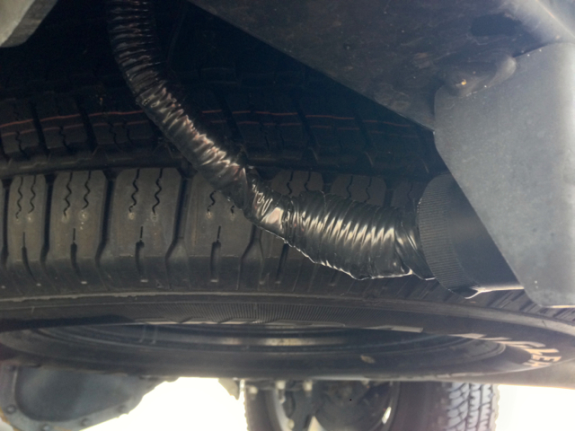
That's from under the truck with the loom coming down the back of the wheel well.
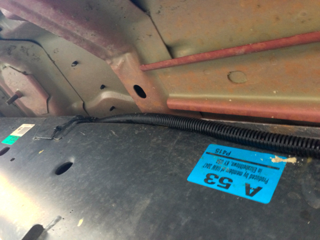
Next I ran it down the truck on top of the passenger frame rail, securing it with long zip ties.
When you get to the back of the truck, you may run out of plastic loom. You can easily buy more from any hardware store, but you don't need it.
Now that you've made it to the back of the truck, those 5 wires (two blacks, two reds, one white) are going to split. one red/black pair will go to the passenger side light, the other pair to the driver side light.
The white wire is your reverse wire. This you need to tap into the 7 pin trailer wiring harness.
Your 7 pin should have the reverse power in the middle wire.
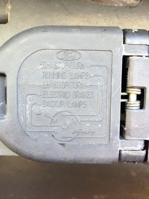
Unwrap the tape around the loom to gain access to the middle wire, tap in, then wrap it back up.
Well there you go, those were the basics of the wiring. From here it's up to you to customize the application to your needs.
.
That's from under the truck with the loom coming down the back of the wheel well.
Next I ran it down the truck on top of the passenger frame rail, securing it with long zip ties.
When you get to the back of the truck, you may run out of plastic loom. You can easily buy more from any hardware store, but you don't need it.
Now that you've made it to the back of the truck, those 5 wires (two blacks, two reds, one white) are going to split. one red/black pair will go to the passenger side light, the other pair to the driver side light.
The white wire is your reverse wire. This you need to tap into the 7 pin trailer wiring harness.
Your 7 pin should have the reverse power in the middle wire.
Unwrap the tape around the loom to gain access to the middle wire, tap in, then wrap it back up.
Well there you go, those were the basics of the wiring. From here it's up to you to customize the application to your needs.
.
Last edited by goneMINIcrazy; 05-17-2014 at 11:42 AM.
The following users liked this post:
SS308 (05-16-2016)
05-16-2014, 11:18 PM
#3
Member
Thread Starter
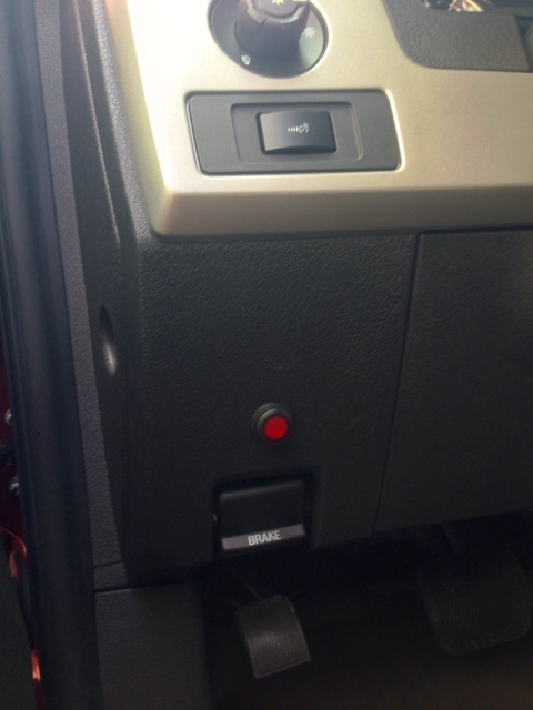
Now for mounting the switch and lights.
Here's where I put my switch.
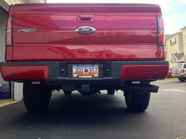
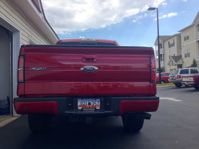
And there's the big question of how to mount the lights. There are plenty of options. You can drill a hole in the shackle mount and hang it from there, or you can mount it directly under the bumper. I didn't want to hang it from the shackle because I didn't want to drill into anything. I didn't want to hang them from the bumper because that meant blinding anyone behind my truck at night.
I opted to design my own little system. I bought some flat aluminum from Lowe's, and cut it up and made my own mounts. Here was the result.
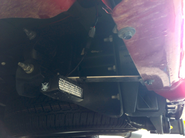
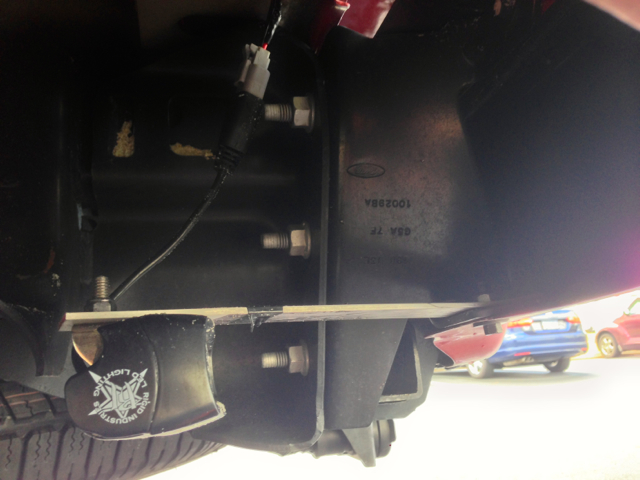
Because they are aluminum they won't bend in regular use, but if I ever need to adjust the position of the light, all it requires is a little force. This is especially helpful when camping, it allows me to get MAXIMUM light while off road, but when we get back to civilization, I can easily bend them back up so the the bottom of the bumper cuts off the light pattern at about 4 ft. That is the perfect pattern for the application, more than enough to see when backing up, but not so high that I blind poor old betty in her cadillac in the parking lot.
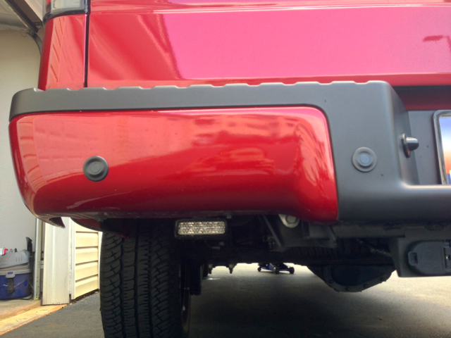
You can see here the lights a perfectly visible at a low angle, but the moment you move above 4 ft the lights are hidden completely.
Here's where I put my switch.
And there's the big question of how to mount the lights. There are plenty of options. You can drill a hole in the shackle mount and hang it from there, or you can mount it directly under the bumper. I didn't want to hang it from the shackle because I didn't want to drill into anything. I didn't want to hang them from the bumper because that meant blinding anyone behind my truck at night.
I opted to design my own little system. I bought some flat aluminum from Lowe's, and cut it up and made my own mounts. Here was the result.
Because they are aluminum they won't bend in regular use, but if I ever need to adjust the position of the light, all it requires is a little force. This is especially helpful when camping, it allows me to get MAXIMUM light while off road, but when we get back to civilization, I can easily bend them back up so the the bottom of the bumper cuts off the light pattern at about 4 ft. That is the perfect pattern for the application, more than enough to see when backing up, but not so high that I blind poor old betty in her cadillac in the parking lot.
You can see here the lights a perfectly visible at a low angle, but the moment you move above 4 ft the lights are hidden completely.
05-16-2014, 11:21 PM
#4
Member
Thread Starter
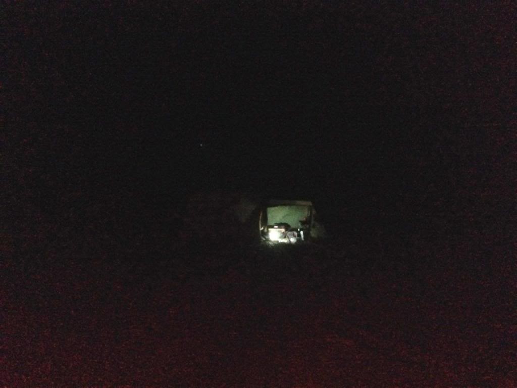
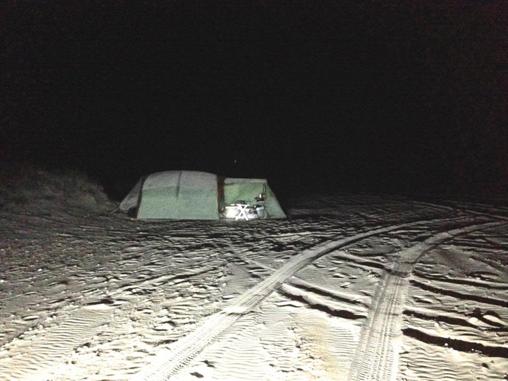
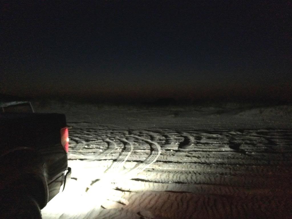
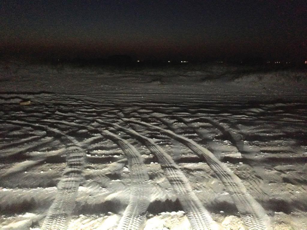
Finally here's some shots of the lights in action from our recent camping trip on the beach at Cape Lookout, NC.
That's our tent with a lantern on. It was pitch black btw.
And here it is with the backup lights turned on.
It's about 50-75 ft from the back of the truck to the tent. I'm standing about 6 ft behind the truck for the picture.
Couple more pics from the night before. You see the canopy? The top part is 12x12 so that should give you some scale. This was about 50-60ft I think and was just a half hour after sunset.
05-17-2014, 01:05 AM
#5

Moved and approved!
05-17-2014, 01:06 AM
#6
Member
Thread Starter
05-17-2014, 11:44 AM
#7
Member
Thread Starter
Anyone who has any suggestions/corrections, let me know, hopefully we can make this a foolproof design.
Trending Topics
The following users liked this post:
goneMINIcrazy (06-04-2014)
05-26-2014, 12:59 PM
#9
Member
Thread Starter
EDIT: Ok so Rigid recommends you DO NOT install the relay under the hood. They say it MUST be under the dash for fear of moisture and temperatures. I for one, COULD NOT figure out how to get the damn thing in there.... Anyone who has a better idea please share....
I just bought a 10 pack of relays for $10 so if the relay ever blows, I'll have plenty of backups.
.
I just bought a 10 pack of relays for $10 so if the relay ever blows, I'll have plenty of backups.
.

