Coin Holder Mod - "Changed" to Clock. 12.10.2013. Pic Heavy.
 12-11-2013, 12:23 AM
#1
Member
Thread Starter


I finally got a chance to replace the infamous coin holder today.
I replaced it with an Auotmeter Clock.
The following is how I performed the task and what wires I used to power the unit. My method works for me but, may not work for you. I fail at soldering so usually I opt for the crimping method where I can.
I have researched forums for ideas and information. Where I seemed to come up short was the information about the location of a wire to allow aftermarket accessories to be dimmed using the stock dimmer control for the instrument lighting. I *think* I remembered reading it a couple of months ago, but could not find it again.
I purchased the Autometer Clock from Summit Racing. I was in the area today so I stopped in and picked up a few things.
I bought the Autometer Clock, Part Number: 1385. I believed this unit was as close as I could get to it matching the stock gauges.
The clock was $61.97 at Summit Racing.
Here is a link to the Autometer website -
http://www.autometer.com/cat_gaugede...id=2972&sid=17
Here is a picture of the contents of the box.
1 each clock.
1 each Grommet.
2 each knurled ***** with star washers.
1 each RED bulb cover.
1 each GREEN bulb cover.
Instruction sheet.
Assortment of Autometer stickers.
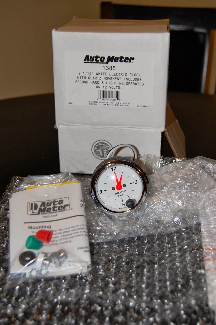
Closer view of the clock.

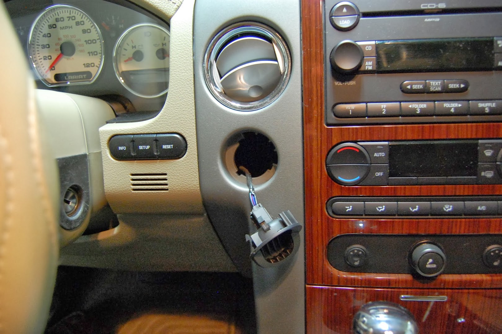
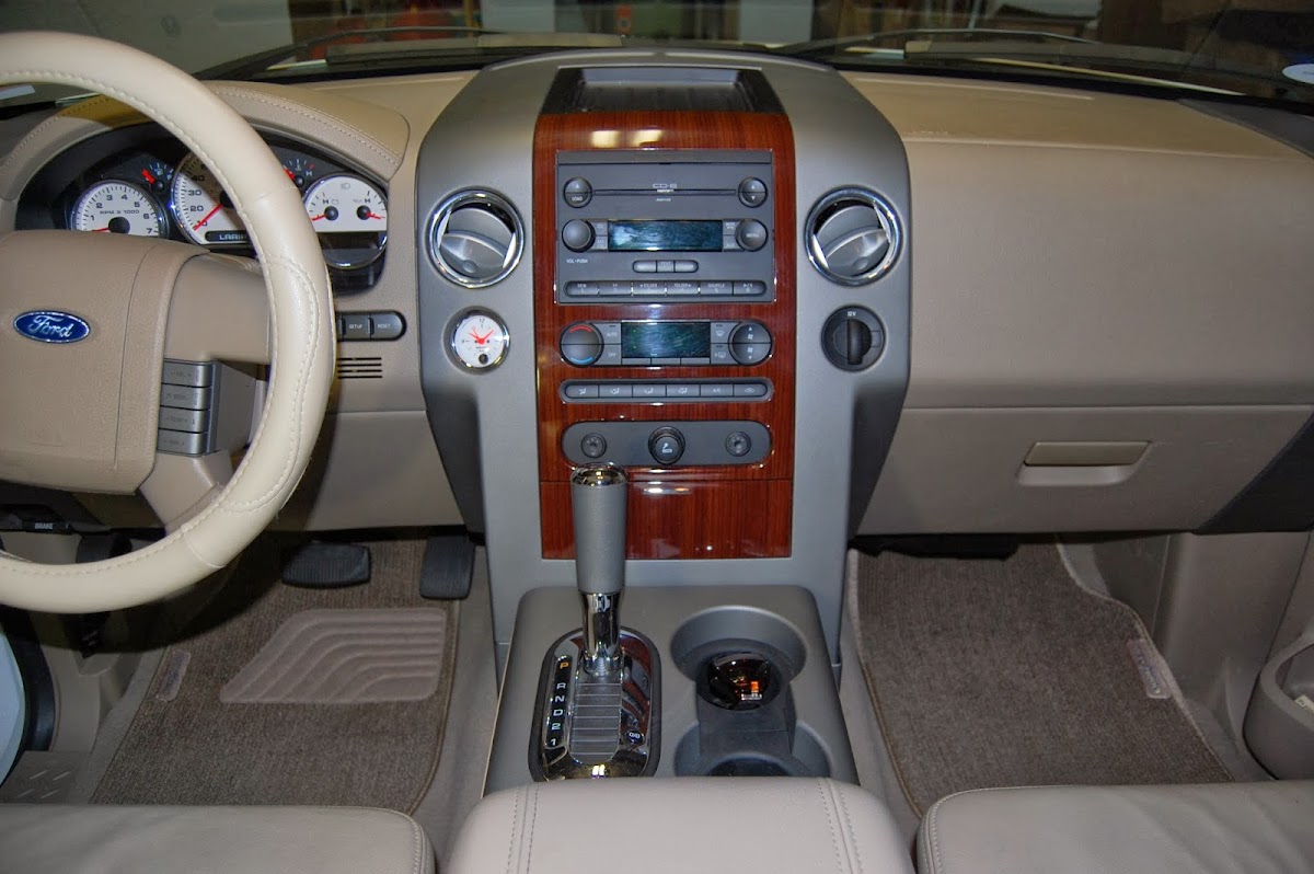
BEFORE - Overview of the dash with the coin holder installed to the left of the air conditioning control panel.

Here I have removed the coin holder.
Using one hand, I used a small screwdriver to get under the edge of the holder. With the other, I simply pulled on the coin holder. It popped off easily.
The wires that you see plugged into the back of the coin holder is the connector for the Four Wheel Drive (4x4) option on the truck.
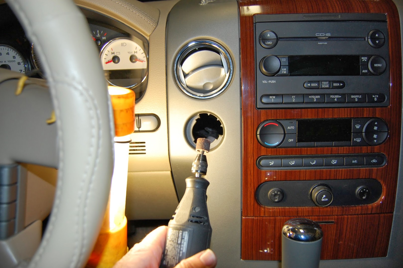
I used a Dremel tool with a sanding disk to start to remove excess material from the edge of the opening to allow the clock to fit.
Remove a little - test fit - repeat.
In hind sight, it would have been a good idea to have a vacuum cleaner running with the nozzle near the work area of the Dremel.
This would have prevented a lot of dust scatter in the immediate area.
It would have also helped with dusting behind the dash.
Test fitting the clock.
Here is a shot of the opening with the excess material removed.

Here is a shot of the Four Wheel Drive connector.
I used two wires from this connector.
The lower wire - Blue and Red is the power wire that is controlled by the dimmer switch for the instrument lights.
The solid Black wire is a Ground wire.

I replaced it with an Auotmeter Clock.
The following is how I performed the task and what wires I used to power the unit. My method works for me but, may not work for you. I fail at soldering so usually I opt for the crimping method where I can.
I have researched forums for ideas and information. Where I seemed to come up short was the information about the location of a wire to allow aftermarket accessories to be dimmed using the stock dimmer control for the instrument lighting. I *think* I remembered reading it a couple of months ago, but could not find it again.
I purchased the Autometer Clock from Summit Racing. I was in the area today so I stopped in and picked up a few things.
I bought the Autometer Clock, Part Number: 1385. I believed this unit was as close as I could get to it matching the stock gauges.
The clock was $61.97 at Summit Racing.
Here is a link to the Autometer website -
http://www.autometer.com/cat_gaugede...id=2972&sid=17
Here is a picture of the contents of the box.
1 each clock.
1 each Grommet.
2 each knurled ***** with star washers.
1 each RED bulb cover.
1 each GREEN bulb cover.
Instruction sheet.
Assortment of Autometer stickers.
Closer view of the clock.
BEFORE - Overview of the dash with the coin holder installed to the left of the air conditioning control panel.
Here I have removed the coin holder.
Using one hand, I used a small screwdriver to get under the edge of the holder. With the other, I simply pulled on the coin holder. It popped off easily.
The wires that you see plugged into the back of the coin holder is the connector for the Four Wheel Drive (4x4) option on the truck.
I used a Dremel tool with a sanding disk to start to remove excess material from the edge of the opening to allow the clock to fit.
Remove a little - test fit - repeat.
In hind sight, it would have been a good idea to have a vacuum cleaner running with the nozzle near the work area of the Dremel.
This would have prevented a lot of dust scatter in the immediate area.
It would have also helped with dusting behind the dash.
Test fitting the clock.
Here is a shot of the opening with the excess material removed.
Here is a shot of the Four Wheel Drive connector.
I used two wires from this connector.
The lower wire - Blue and Red is the power wire that is controlled by the dimmer switch for the instrument lights.
The solid Black wire is a Ground wire.
Last edited by Stickman81; 12-11-2013 at 12:54 AM.
 12-11-2013, 12:38 AM
#2
Member
Thread Starter
Continued -
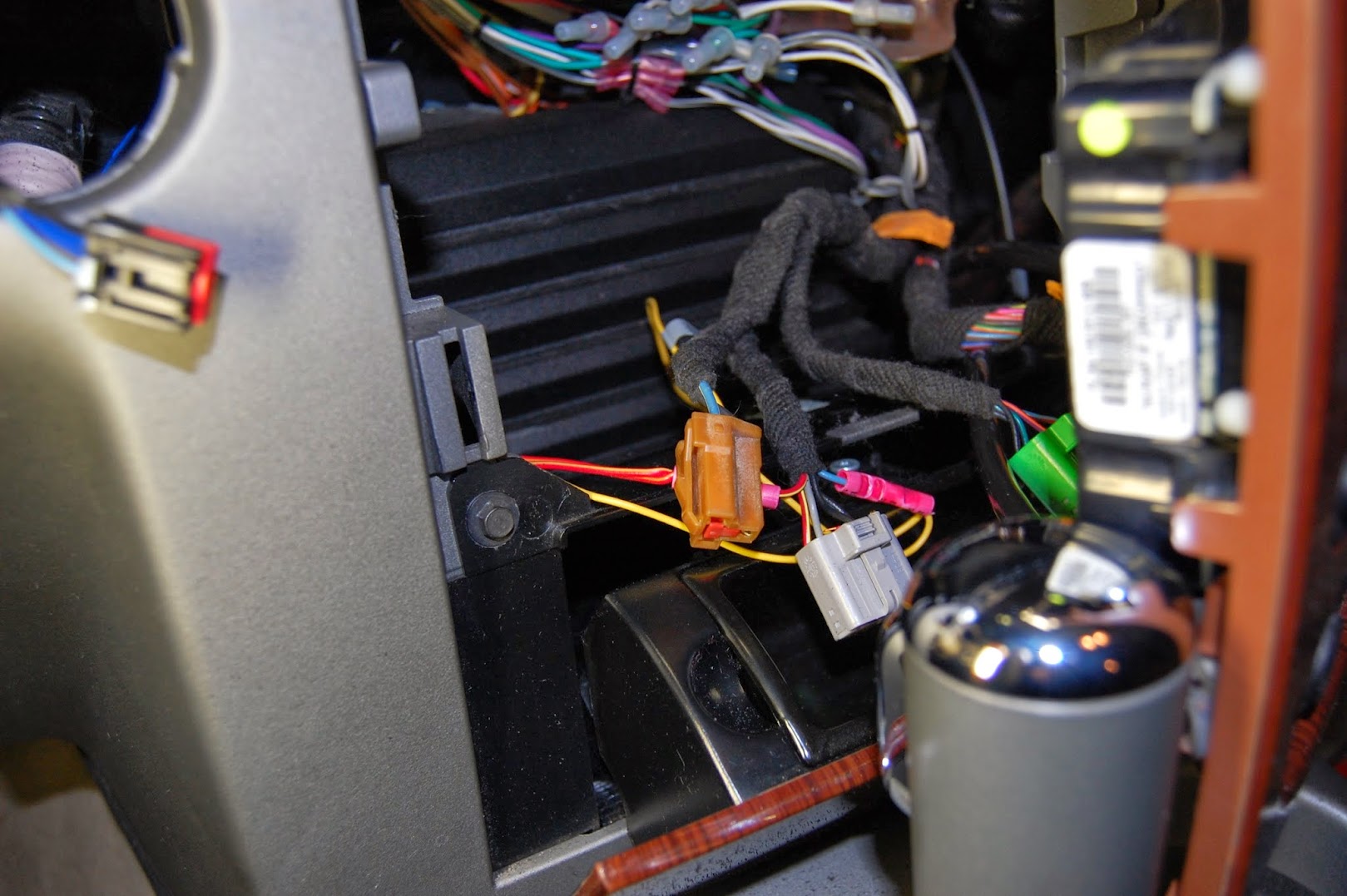
In this picture you can see the Four Wheel Drive connector in the left side.
Towards the right side you can see the wiring for the aftermarket seat heaters I installed last week. The two yellow wires ("Night Light") are for the seat icon on the switch. I had hooked them to what I thought was the best option in that set of connectors. As it turns out, the seat icons illuminated with the courtesy lights. While they did dim, they looked out of place before actually turning on the lights.
I moved the two yellow wires ("Night Light") to the Blue and Red wire at the Four Wheel Drive connector.
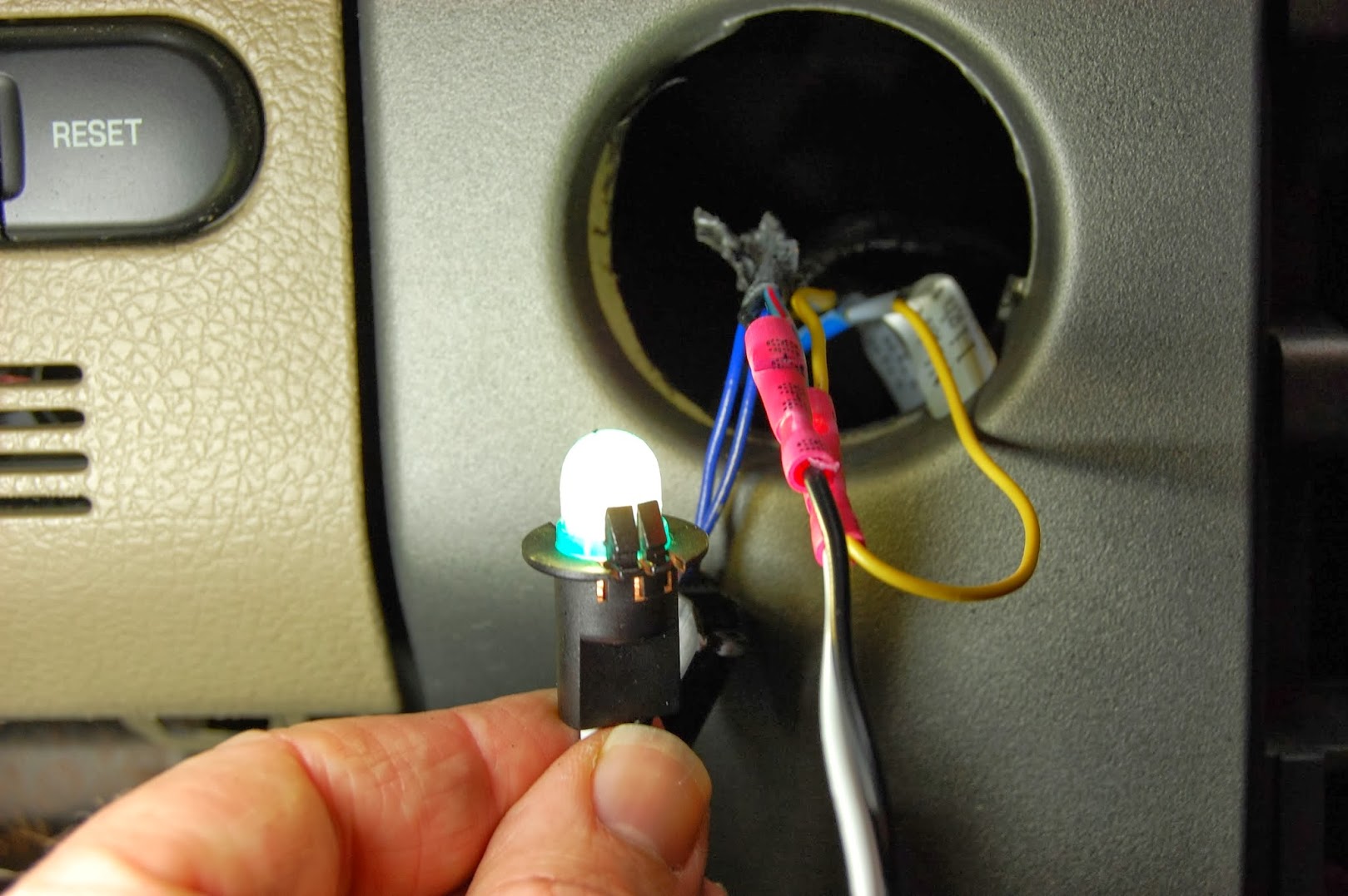
Here is a shot of the seat heater yellow wires and, the clock white wire tied to the blue and red wire. This will give control of the lights by the instrument light dimmer.

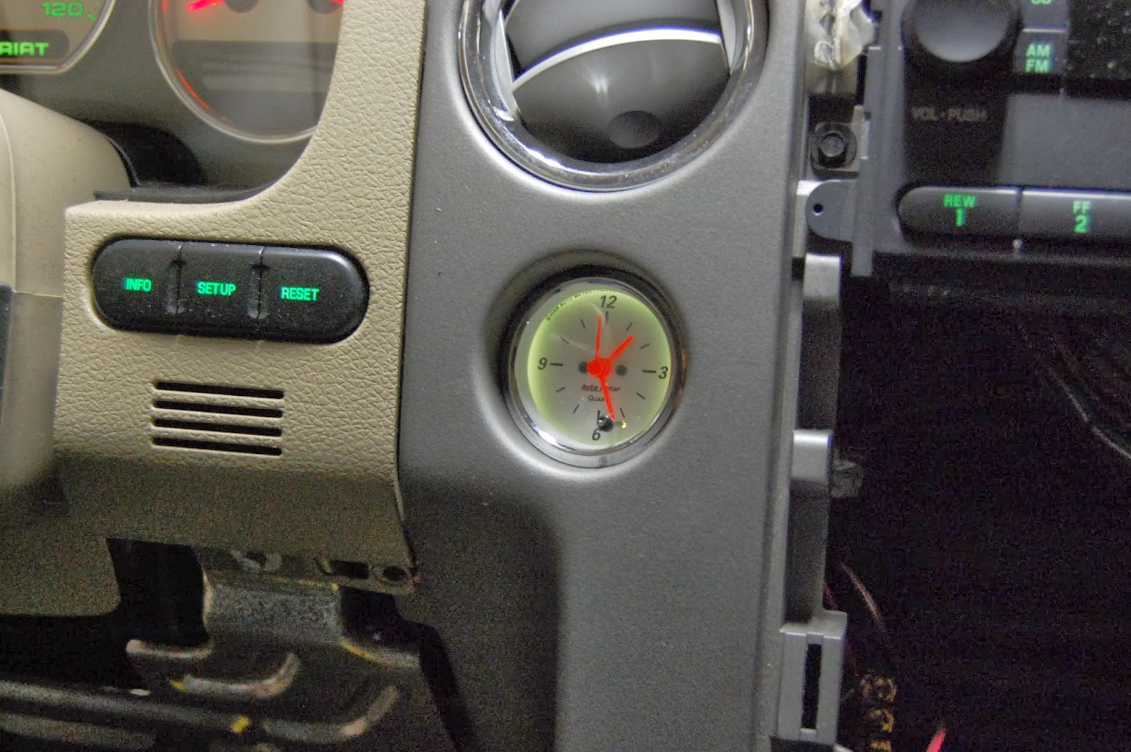
Testing the clock light on the highest setting and the lowest setting using the dimmer switch.

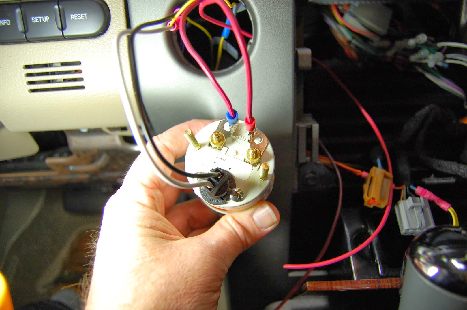
Here is a shot of the backside of the clock.
The white wire is the power wire for the light.
The black wire is the ground wire for the light.
The following two wires and connectors were not included.
I had extra wire and connectors that I used for the power and ground for the clock.
The red wire with red spade connector is for constant power for the clock.
The red wire with the blue spade connector is ground for the clock.
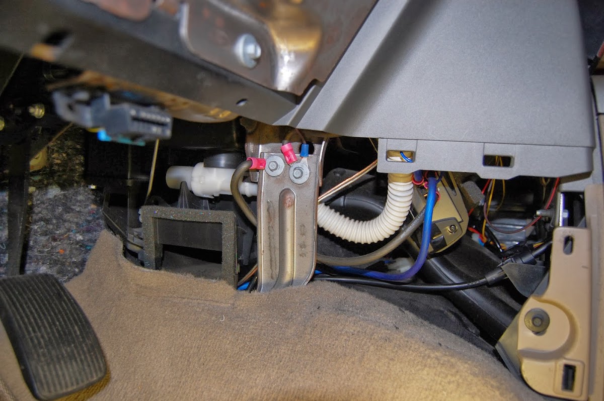
Here is where I grounded the clock ground wire at.
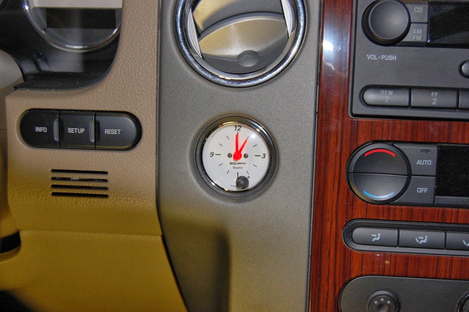
Testing the lighting and fit of the clock.
Notice all the dust from using the Dremel tool to sand the excess dash material.

The following users liked this post:
bobkyle2 (12-11-2013)


 12-11-2013, 12:56 AM
#4

Looks amazing , Jim!
