Custom E-Fan Installation
 04-07-2010, 12:11 PM
#1
Junior Member
Thread Starter

Join Date: Mar 2010
Location: Maryland
Posts: 18
Likes: 0
Received 0 Likes
on
0 Posts
After reading several of the E-Fan write-ups on here I thought it would be a good idea to try to install them myself. I have done it differently then the ones I have seen on here before.

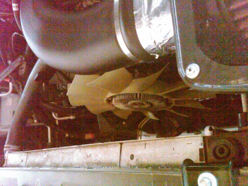
Taking the mechanical fan out was pretty much cut and dry. I went to the local Autozone and rented the removal tools.
Attachment 15979
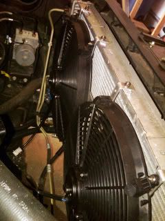
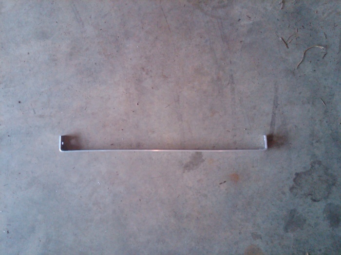
The next large task was figuring out how to mount the 2- 16" fans without possibly damaging the radiator. I was surprised to find that the aluminum radiator bracket had about an 1/2 inch lip. I decided that I could use that lip to mount the brackets.
I then purchased 4- 1/8" pieces of aluminum strips. I bet the ends of the aluminum strips to the shape of the aluminum radiator housing.
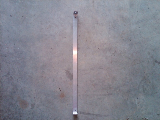

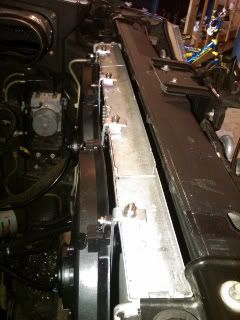
I then pre-drilled the mounting holes for the fan bolts and straps(optional - safety). I tested the bracket before installing on the radiator. Notice that I also used 2 brackets from each fan to help limit vibration.
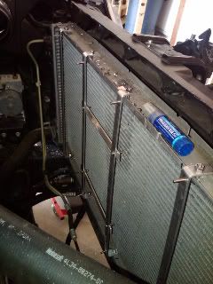
The next step was to drill the 8 holes through the radiator bracket (becareful not to drill into the radiator!). I also recommend using blue lock-tight. You dont want your fans to work their way lose after awhile.
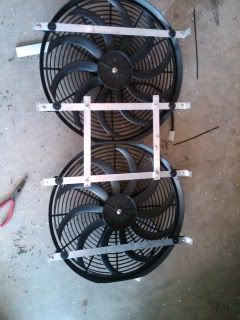
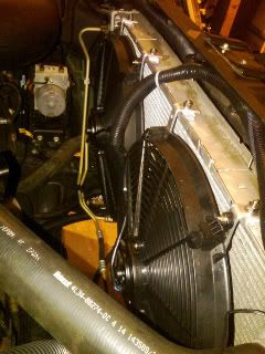
Now we attach the Fans to the brackets using the pre-drilled holes. Notice I already have the bolts in place waiting on the Fans.
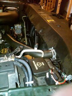
From here we are now able to start doing the electrical. I mounted my fan controller on the top of the windshield fluid reservoir. This appeared to be the best location inside the engine compartment free of moister and any direct heat.

I placed all the wire in wire loom and soldered all connections. Soldering is far the best way to ensure the best connection.

From here I started to route the wires into the cab for the manual switches. I wanted to install 2 switches and 1 LED light.
Switch 1 = Manual ON (bypassing the fan controller) *this connection you must install and inline fuse since it is not protected by the controller fuse*
*optional
Switch 2 = Manual OFF (bypassing the fan controller) This allows for me to turn off the fans even though the controller is sending power to the fans. This is for when you are at a drive though and the fans are screaming. *optional
LED light illuminates when the fans are engaged.
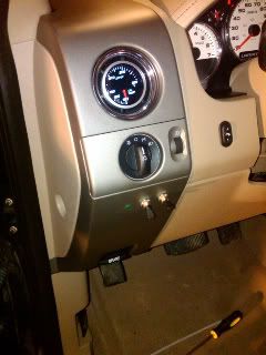
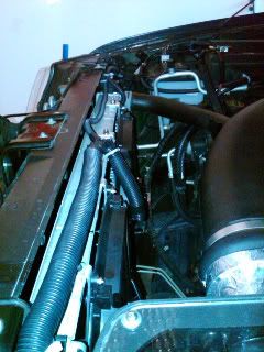
And this is what it looks like in the end.
These are the items I used for this system:
Derale Adjustable Fan Controller #16759 (for dual electric fans up to 25 continuous amps 150 - 240 degrees F). This setup comes with the radiator fin probe. I highly recommend getting the 3/8 NPT thread sensor (derale #16750) along with the Autom Meter Hose adapter (auto meter #2283). I will be switching to this new sensor soon. I believe it would be more accurate.
ProComp 16" Curved Blade fans (2) Part # PC-2054-s
2- 30 amp switches
1- LED Light
1- inline 30 amp fuse
4- 1/8 Aluminum strips
Several stainless steel nuts and bolts.
Taking the mechanical fan out was pretty much cut and dry. I went to the local Autozone and rented the removal tools.
Attachment 15979
The next large task was figuring out how to mount the 2- 16" fans without possibly damaging the radiator. I was surprised to find that the aluminum radiator bracket had about an 1/2 inch lip. I decided that I could use that lip to mount the brackets.
I then purchased 4- 1/8" pieces of aluminum strips. I bet the ends of the aluminum strips to the shape of the aluminum radiator housing.

I then pre-drilled the mounting holes for the fan bolts and straps(optional - safety). I tested the bracket before installing on the radiator. Notice that I also used 2 brackets from each fan to help limit vibration.
The next step was to drill the 8 holes through the radiator bracket (becareful not to drill into the radiator!). I also recommend using blue lock-tight. You dont want your fans to work their way lose after awhile.
Now we attach the Fans to the brackets using the pre-drilled holes. Notice I already have the bolts in place waiting on the Fans.
From here we are now able to start doing the electrical. I mounted my fan controller on the top of the windshield fluid reservoir. This appeared to be the best location inside the engine compartment free of moister and any direct heat.
I placed all the wire in wire loom and soldered all connections. Soldering is far the best way to ensure the best connection.
From here I started to route the wires into the cab for the manual switches. I wanted to install 2 switches and 1 LED light.
Switch 1 = Manual ON (bypassing the fan controller) *this connection you must install and inline fuse since it is not protected by the controller fuse*
*optional
Switch 2 = Manual OFF (bypassing the fan controller) This allows for me to turn off the fans even though the controller is sending power to the fans. This is for when you are at a drive though and the fans are screaming. *optional
LED light illuminates when the fans are engaged.
And this is what it looks like in the end.
These are the items I used for this system:
Derale Adjustable Fan Controller #16759 (for dual electric fans up to 25 continuous amps 150 - 240 degrees F). This setup comes with the radiator fin probe. I highly recommend getting the 3/8 NPT thread sensor (derale #16750) along with the Autom Meter Hose adapter (auto meter #2283). I will be switching to this new sensor soon. I believe it would be more accurate.
ProComp 16" Curved Blade fans (2) Part # PC-2054-s
2- 30 amp switches
1- LED Light
1- inline 30 amp fuse
4- 1/8 Aluminum strips
Several stainless steel nuts and bolts.
Last edited by rye; 04-07-2010 at 01:50 PM.


Trending Topics
 06-21-2010, 07:25 PM
#9
Junior Member

Join Date: Jun 2010
Posts: 11
Likes: 0
Received 0 Likes
on
0 Posts
Whats the point of removing the stock fan and replacing with 2 electric fans? And as asked above, do these fans automatically activate or do they need a switch installed in the cab to turn them off/on?
06-21-2010, 07:34 PM
#10
Senior Member
The controller turns the fans on when the sensed temperature reaches a preset level, and off when it gets back down to a lower preset level. His switches are just for overriding the controller if he wants to.