Intake Manifold Removal
 01-29-2014, 03:45 PM
#1

Intake Manifold Removal-
I will post up part #'s for the gaskets and tools needed later. Too tired right now.
1) Disconnect the negative battery terminal. (If you are draining the entire system wait until after step 2)
( I think its easier to remove the entire battery to move stuff around) .
*** I find it a lot easier to remove the fan/shroud and radiator to do this***
You have a lot of room and can stand in the bay.
If you need notes on that, check out this thread for the steps.
2) Drain the cooling system.
Instead of draining each side of the block, use the radiator plug at the bottom passenger side to drain the radiator. First, place a 3 gallon bucket under the plug. Then let the truck idle until the thermostat opens up to drain the remaining fluid. **Make sure to keep an eye on the temp. gauge and not let it get above half way.**
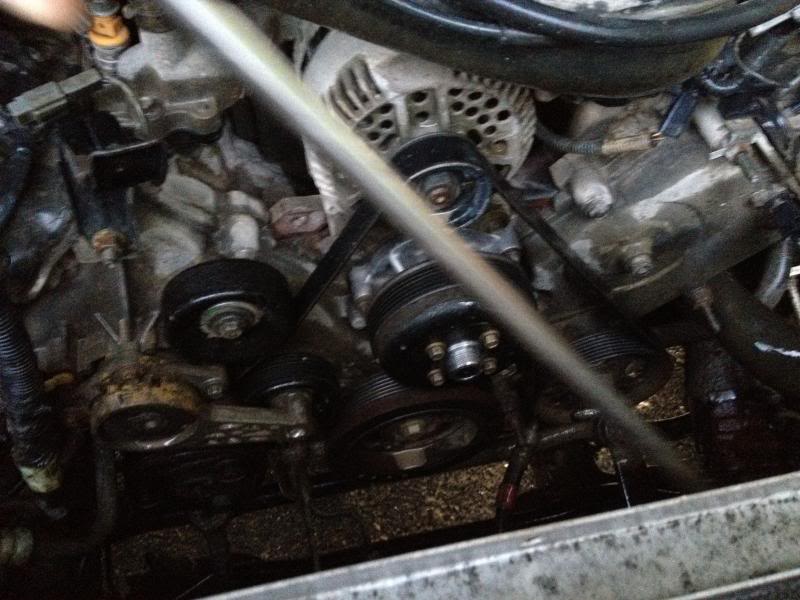
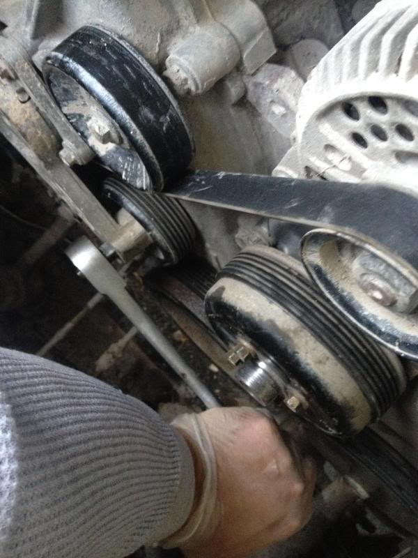
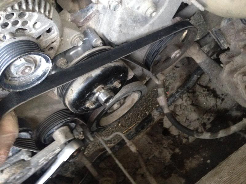
3) Remove the drivebelt.
Simply use a �� ratchet on the tensioner pulley and press down to relieve pressure. Once you remove pressure you will be able to pull the belt off the alternator pulley, thus being able to remove the entire belt.
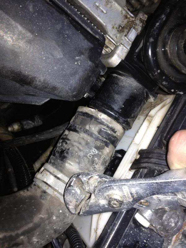
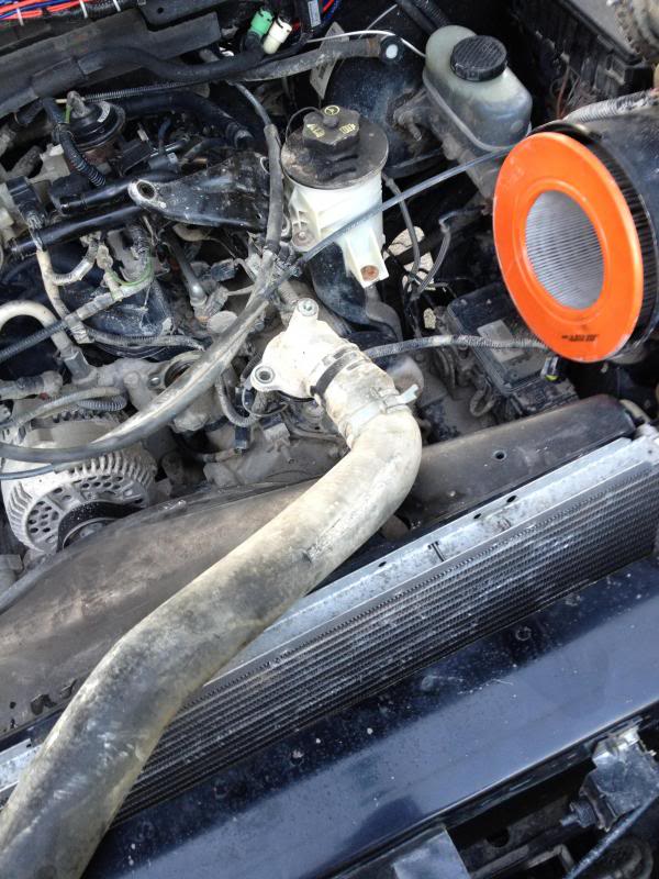
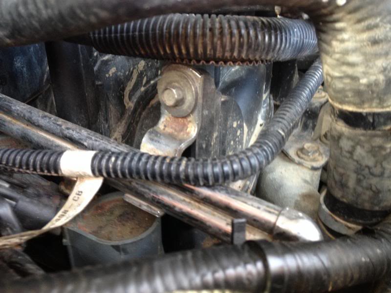
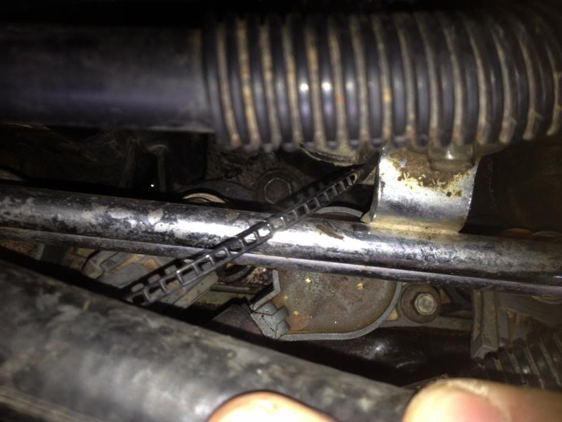
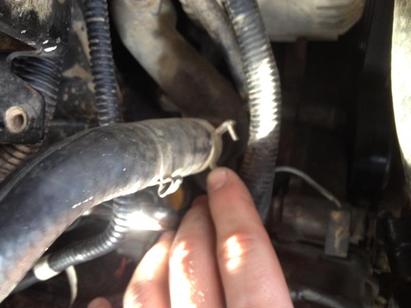
4) Removing coolant lines and thermostat housing.
First disconnect the radiator hose from the thermostat housing. Use a pair of pliers or other appropriate tool to move the clamp and pull the hose off.
It is located here:
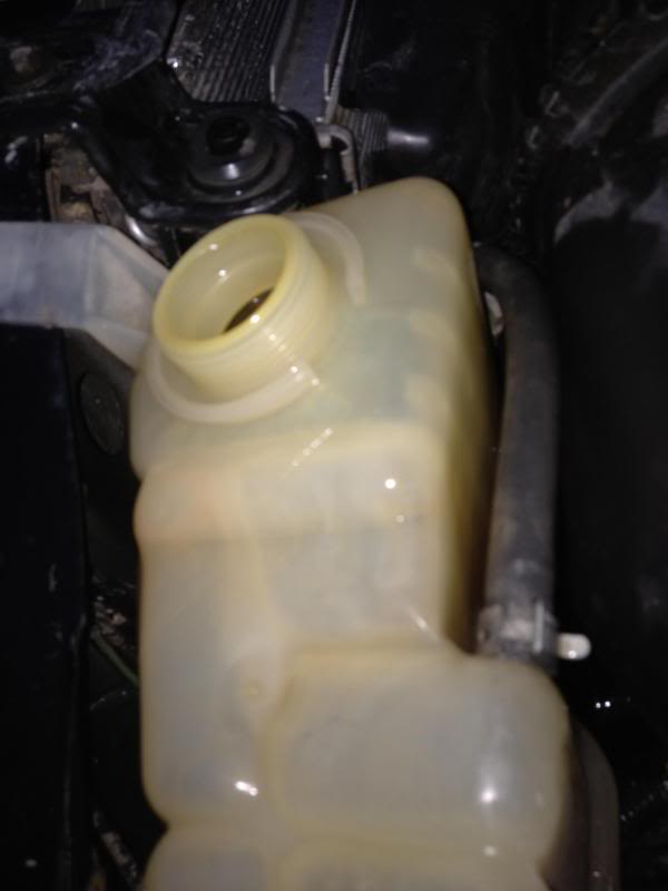
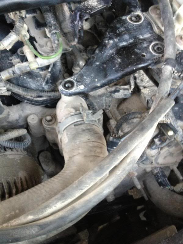
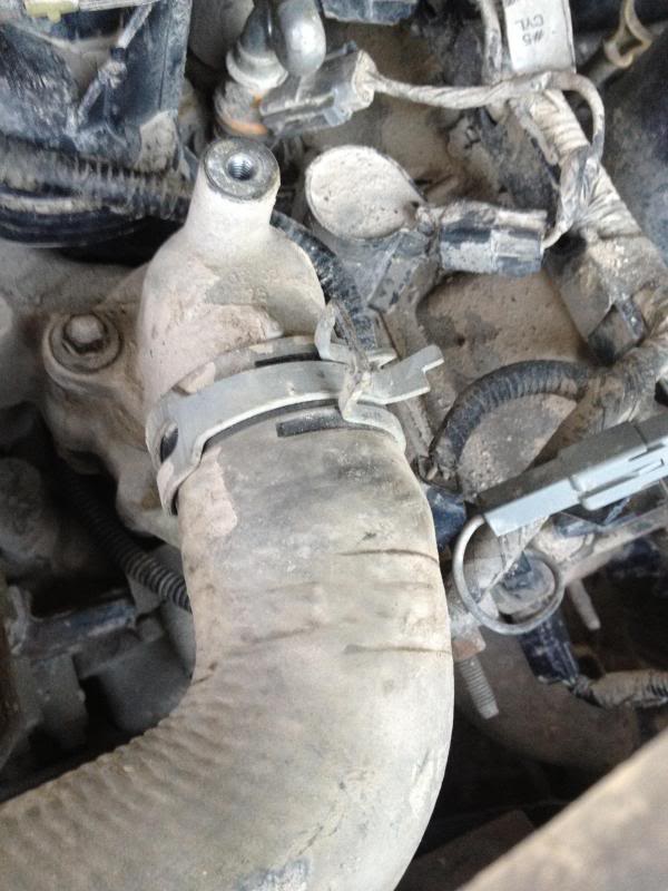
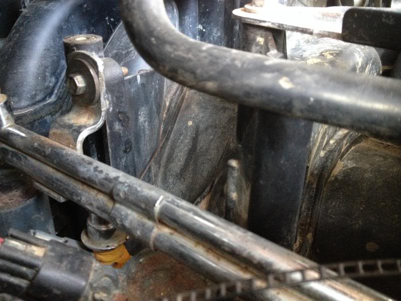
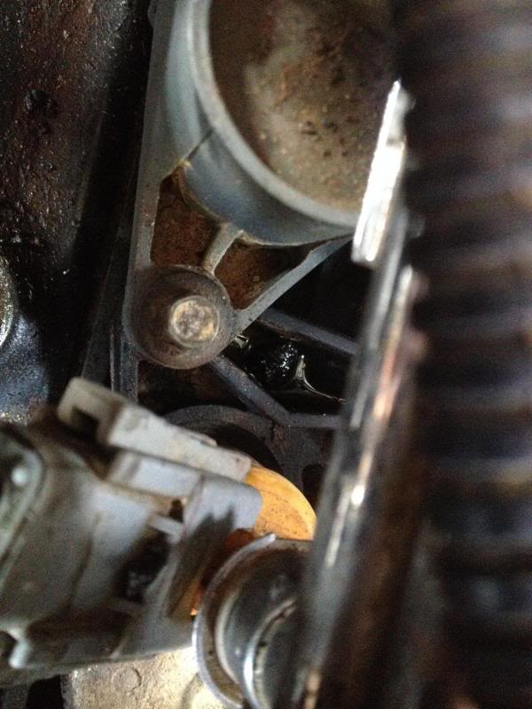
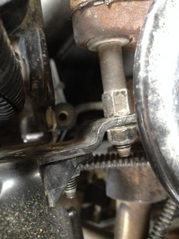
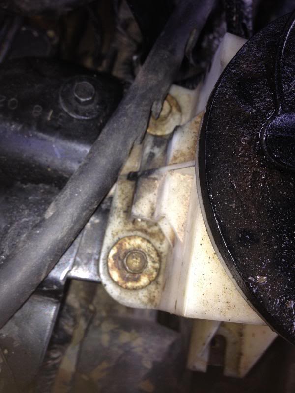
5) Disconnect the power steering fluid reservoir and holder from the thermostat housing.
There are 2-8mm bolts that hold the reservoir to the mounting plate (which is bolted to the thermostat housing. Remove both bolts, and then remove the single 8mm bolt which attaches the bracket to the top of the thermostat housing (this single bolt is directly on top of the housing). See pictures in part 6 for reference.
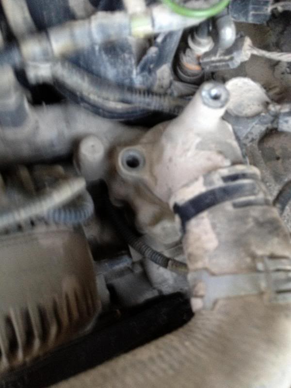
6) Remove the thermostat housing.
Remove both 10mm bolts holding the thermostat housing to the manifold. One on each side.
Note that these bolts also retain the intake manifold and are absolutely necessary to remove. (Check the T-stat O-ring during this as well).
I will post up part #'s for the gaskets and tools needed later. Too tired right now.
1) Disconnect the negative battery terminal. (If you are draining the entire system wait until after step 2)
( I think its easier to remove the entire battery to move stuff around) .
*** I find it a lot easier to remove the fan/shroud and radiator to do this***
You have a lot of room and can stand in the bay.

If you need notes on that, check out this thread for the steps.
2) Drain the cooling system.
Instead of draining each side of the block, use the radiator plug at the bottom passenger side to drain the radiator. First, place a 3 gallon bucket under the plug. Then let the truck idle until the thermostat opens up to drain the remaining fluid. **Make sure to keep an eye on the temp. gauge and not let it get above half way.**

3) Remove the drivebelt.
Simply use a �� ratchet on the tensioner pulley and press down to relieve pressure. Once you remove pressure you will be able to pull the belt off the alternator pulley, thus being able to remove the entire belt.


4) Removing coolant lines and thermostat housing.
First disconnect the radiator hose from the thermostat housing. Use a pair of pliers or other appropriate tool to move the clamp and pull the hose off.
It is located here:

5) Disconnect the power steering fluid reservoir and holder from the thermostat housing.
There are 2-8mm bolts that hold the reservoir to the mounting plate (which is bolted to the thermostat housing. Remove both bolts, and then remove the single 8mm bolt which attaches the bracket to the top of the thermostat housing (this single bolt is directly on top of the housing). See pictures in part 6 for reference.
6) Remove the thermostat housing.
Remove both 10mm bolts holding the thermostat housing to the manifold. One on each side.
Note that these bolts also retain the intake manifold and are absolutely necessary to remove. (Check the T-stat O-ring during this as well).


 01-29-2014, 03:49 PM
#2
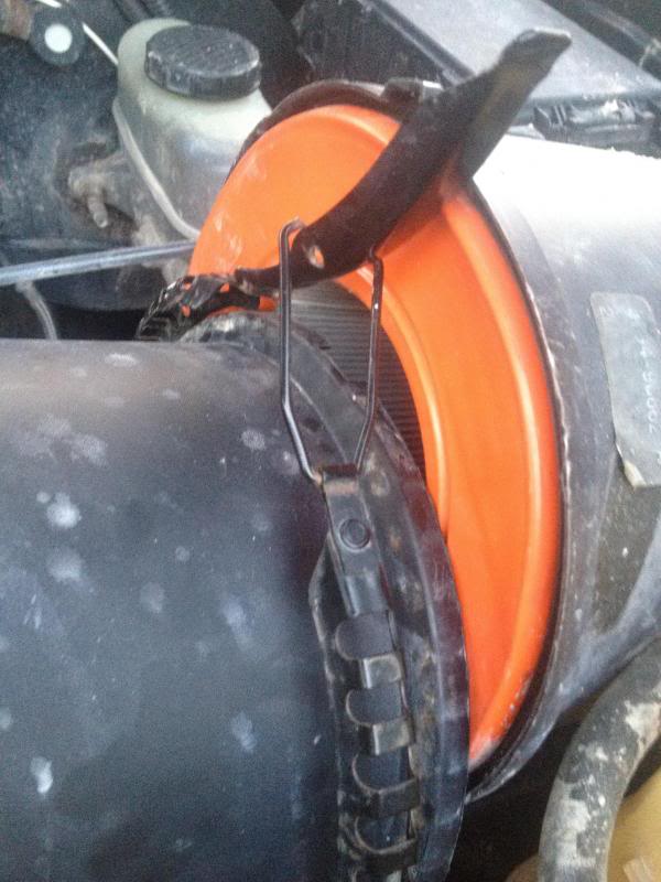
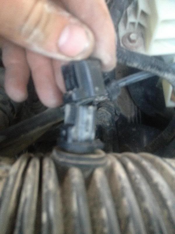
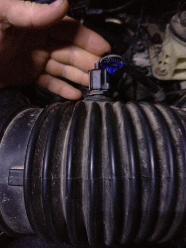
7) Remove the air intake, air cleaner, and outlet tube.
Loosen the 8mm bolt on the hose clamp connecting the intake tube to the throttle body. Remove both lines that are connected about 4 inches away from the throttle body. Then unplug the IAT (Intake Air Temp.) sensor from the corrugated tubing. Now unplug the MAF(Mass air flow) sensor from the connector next to the driver�s side fender well (follow the wires from the sensor to the plug). Once that is done, pull the clamp up on your air filter housing and remove the entire intake tubing and place it out of the way. It is fine to leave the short part which houses the filter and connects to the driver�s side fender well.
8) Labeling vacuum lines and connectors.
Use color coated zip ties and/or tap to label the vacuum lines and connectors. As of right now, we have unplugged the IAT sensor, MAF sensor, ���
Here is an overview of the hoses and lines you will need to label and disconnect from the throttle body. Use this to help with the next several steps to the end:
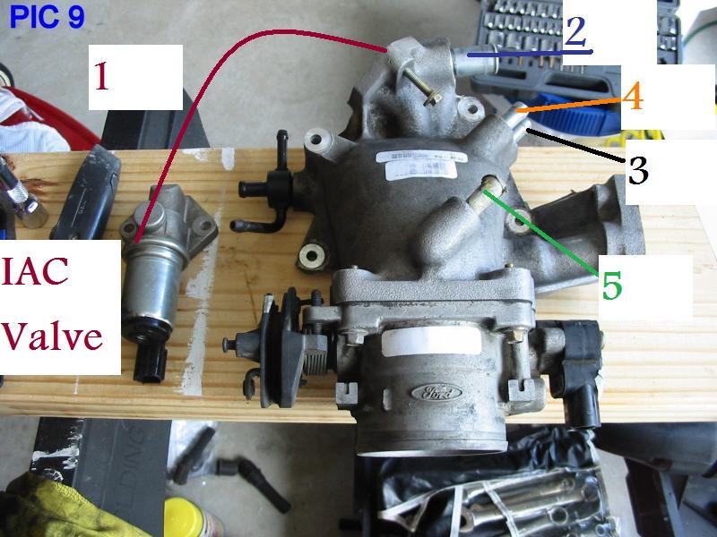
#1 Is the IAC Valve, this is bolted to the back of the throttle body. Dont remove this.
#2 This is the IAC Valve vacuum hose location and goes to the top hose on the plastic intake right before the throttle body.
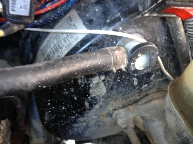
#3 This is the brake booster hose/line that goes to the big circular drum on the drives side firewall.
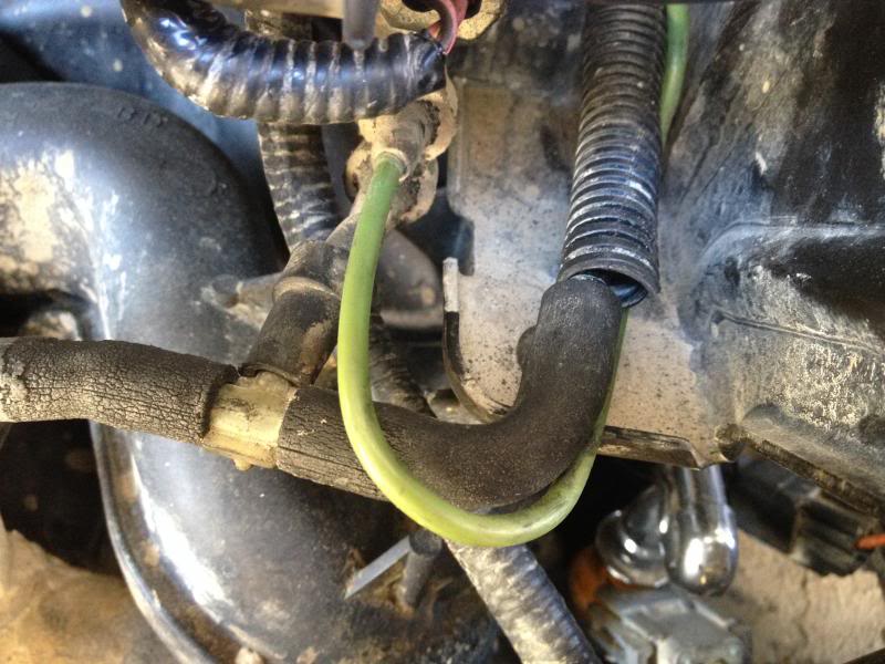
#4 This is the vacuum/hose that goes to the EVR Solenoid. The small green hose in the corrugated tubing is connected to a "T" at the solenoid.
#5 This goes to the purge valve canister and has a green connector on the end of it.
Reguarding the pictures below:
#1/#2
#3
#4
#5
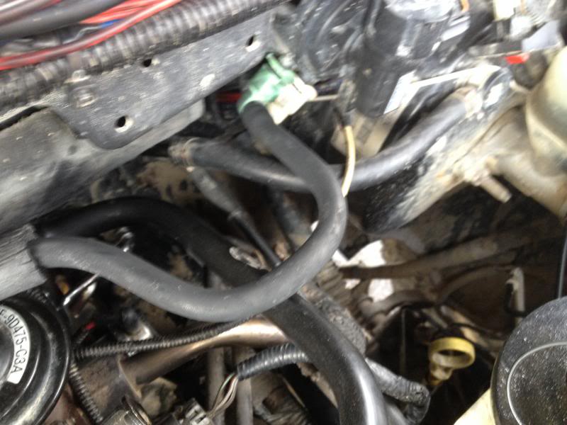
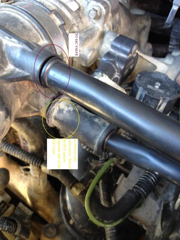
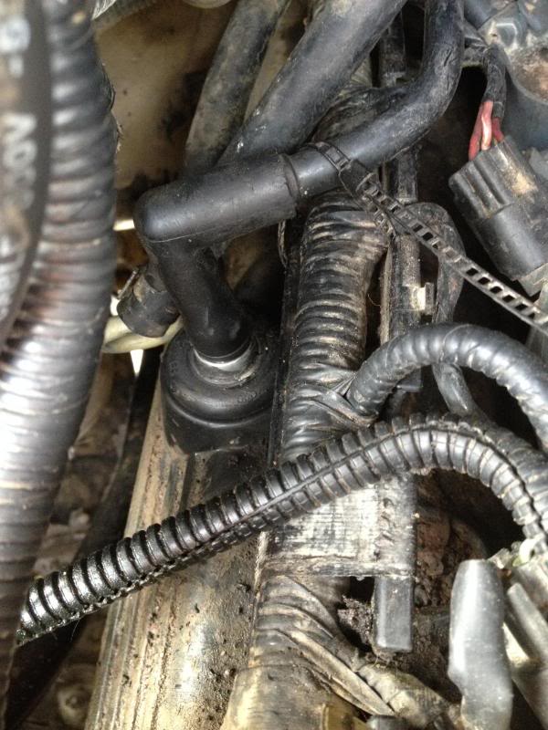
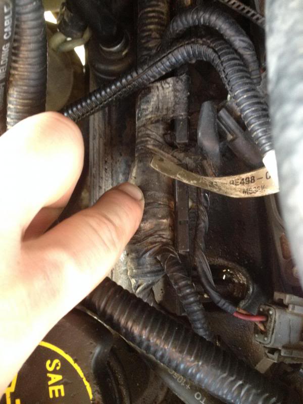
9) Removal of PCV hoses.
First remove the PCV valve cover hose from the passenger�s side valve cover. Next remove the canister purge hose from the driver�s side valve cover. See pictures below for reference and be sure to label these as well.
PCV Valve and eblow/hose
Loosen the 8mm bolt on the hose clamp connecting the intake tube to the throttle body. Remove both lines that are connected about 4 inches away from the throttle body. Then unplug the IAT (Intake Air Temp.) sensor from the corrugated tubing. Now unplug the MAF(Mass air flow) sensor from the connector next to the driver�s side fender well (follow the wires from the sensor to the plug). Once that is done, pull the clamp up on your air filter housing and remove the entire intake tubing and place it out of the way. It is fine to leave the short part which houses the filter and connects to the driver�s side fender well.


8) Labeling vacuum lines and connectors.
Use color coated zip ties and/or tap to label the vacuum lines and connectors. As of right now, we have unplugged the IAT sensor, MAF sensor, ���
Here is an overview of the hoses and lines you will need to label and disconnect from the throttle body. Use this to help with the next several steps to the end:

#1 Is the IAC Valve, this is bolted to the back of the throttle body. Dont remove this.
#2 This is the IAC Valve vacuum hose location and goes to the top hose on the plastic intake right before the throttle body.
#3 This is the brake booster hose/line that goes to the big circular drum on the drives side firewall.
#4 This is the vacuum/hose that goes to the EVR Solenoid. The small green hose in the corrugated tubing is connected to a "T" at the solenoid.
#5 This goes to the purge valve canister and has a green connector on the end of it.
Reguarding the pictures below:
#1/#2

#3

#4

#5

9) Removal of PCV hoses.
First remove the PCV valve cover hose from the passenger�s side valve cover. Next remove the canister purge hose from the driver�s side valve cover. See pictures below for reference and be sure to label these as well.
PCV Valve and eblow/hose
 01-29-2014, 03:50 PM
#3
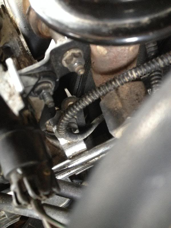
10) Disconnect the throttle cable and cruise control cable linkage.
This is easily done by the following:
a) Remove the spring that governs the throttle and pulls the cable back. (This is self explanatory, use a pair of pliers)
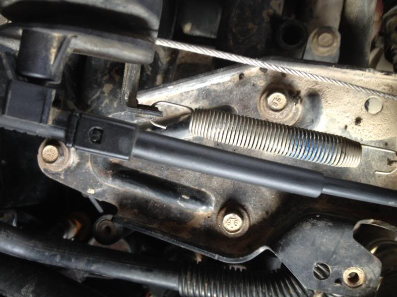
b) Pull back on the throttle by hand, then lift the cable up and pull it out of the throttle cable holder.
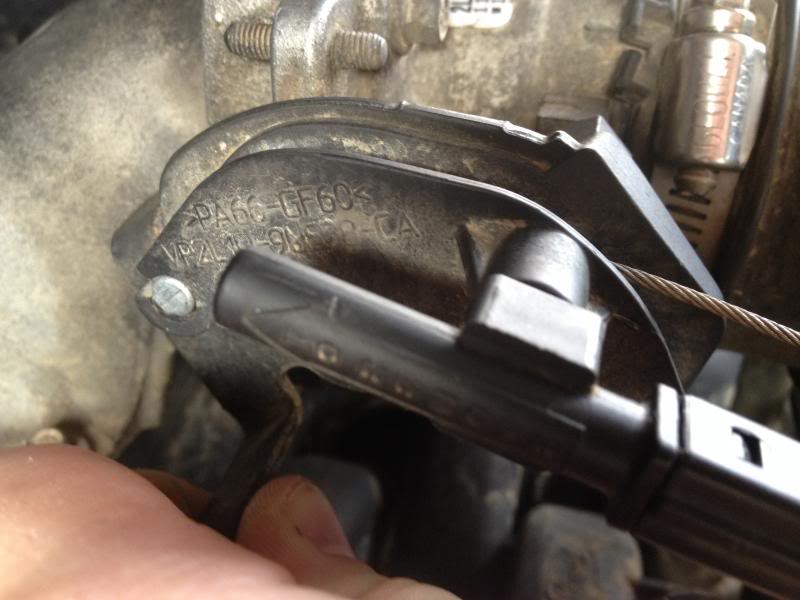
c) The cruise control cable is easily remove by simply pulling the cable vertically and pulling the joint loose from the ball on the throttle assembly.
d) Once those steps are done, leave the brackets/tubing containing and holding the throttle cable and control linkage on the mounting place. Then remove the 3-10mm bolts holding the mounting plate on.
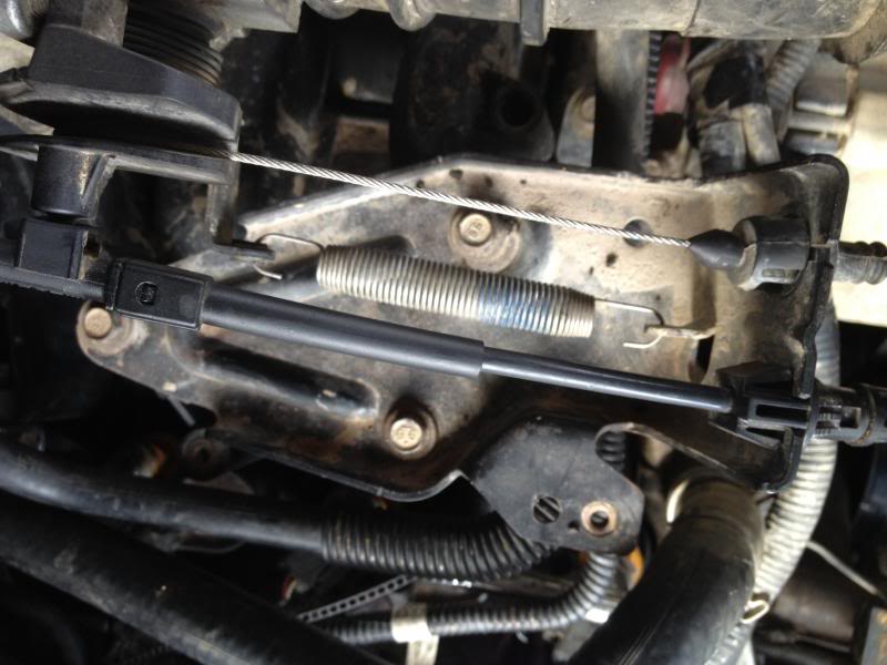
e) Then place the mounting plate with the cables still attached up and out of the way.
11) Remove electrical connectors from throttle body and label them
a) Remove the TPS (Throttle Position Sensor) connector from the housing and label it TPS.
12) Remove Fuel Injector electrical connectors
a) You will have to unplug all 8 fuel injector plugs. This is fairly easy except for # 4 and #8, but shouldn’t be too bad. Simply push in on the connectors and pull them off the injectors. I like to use a market to label each one to make sure I don’t get the confused. Obviously there are four on each side, so label the passenger side 1-4 from the front of the engine to the back.
13) Disconnecting fuel rails.
a) First remove the 2-8mm bolts on both side of the engine holding the fuel rail in place.
b) Once the rails have been unbolted you can leave the injectors on the rails or pull them out.
c) I prefer to pull them off to check for corrosion and bad O-rings, so I recommend pulling them from the fuel rail once it is loosened.
d) Once you get the injectors off the fuel rail(simply held on by the O-rings) you will have a little play to move then out of the way over on each valve cover.
This is easily done by the following:
a) Remove the spring that governs the throttle and pulls the cable back. (This is self explanatory, use a pair of pliers)

b) Pull back on the throttle by hand, then lift the cable up and pull it out of the throttle cable holder.

c) The cruise control cable is easily remove by simply pulling the cable vertically and pulling the joint loose from the ball on the throttle assembly.
d) Once those steps are done, leave the brackets/tubing containing and holding the throttle cable and control linkage on the mounting place. Then remove the 3-10mm bolts holding the mounting plate on.

e) Then place the mounting plate with the cables still attached up and out of the way.
11) Remove electrical connectors from throttle body and label them
a) Remove the TPS (Throttle Position Sensor) connector from the housing and label it TPS.


12) Remove Fuel Injector electrical connectors
a) You will have to unplug all 8 fuel injector plugs. This is fairly easy except for # 4 and #8, but shouldn’t be too bad. Simply push in on the connectors and pull them off the injectors. I like to use a market to label each one to make sure I don’t get the confused. Obviously there are four on each side, so label the passenger side 1-4 from the front of the engine to the back.

13) Disconnecting fuel rails.
a) First remove the 2-8mm bolts on both side of the engine holding the fuel rail in place.


b) Once the rails have been unbolted you can leave the injectors on the rails or pull them out.
c) I prefer to pull them off to check for corrosion and bad O-rings, so I recommend pulling them from the fuel rail once it is loosened.
d) Once you get the injectors off the fuel rail(simply held on by the O-rings) you will have a little play to move then out of the way over on each valve cover.
01-29-2014, 03:51 PM
#4
14) (Optional) Remove ignition wire brackets and mounts from valve covers.
15) Remove the connectors to the COPS/Ignition coils.
a)Use a 7mm socket and long extension to remove all 8 bolts retain the COP (Coil over plugs).
b) Once the bolts are removed disconnect the electrical connector and pull the coils of each cylinder and set them aside. (Check for residue and resistance on the ignition coils.
16) Romove the IAC hose
This hose is connected to the very back of the throttle body and is obviously attached to top line on the intake.
See the overview section above:
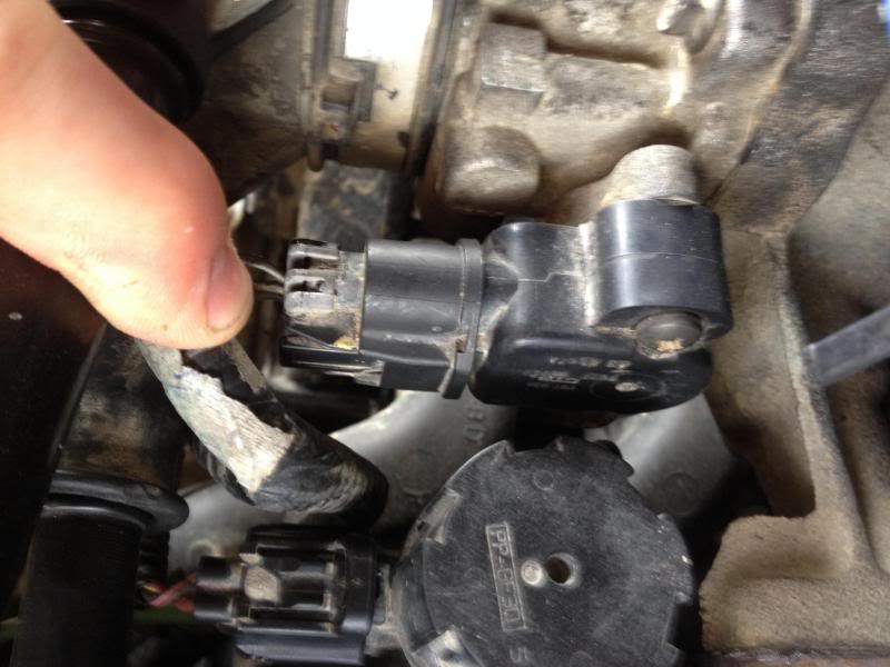
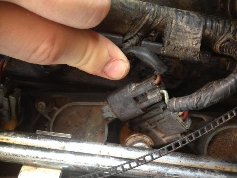
17) Remove the DPFT(Differential feedback transducer), connector and hoses.
a) this is held on by two 8-mm nuts, remove the nuts and label the connector and two small hoses at the bottom.
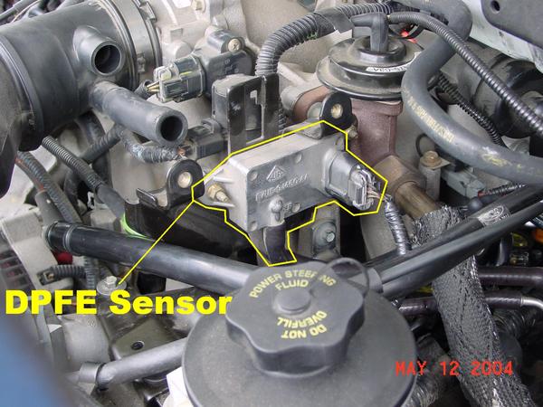
18) Remove engine vacuum regulator sensor.
The connector on the right.
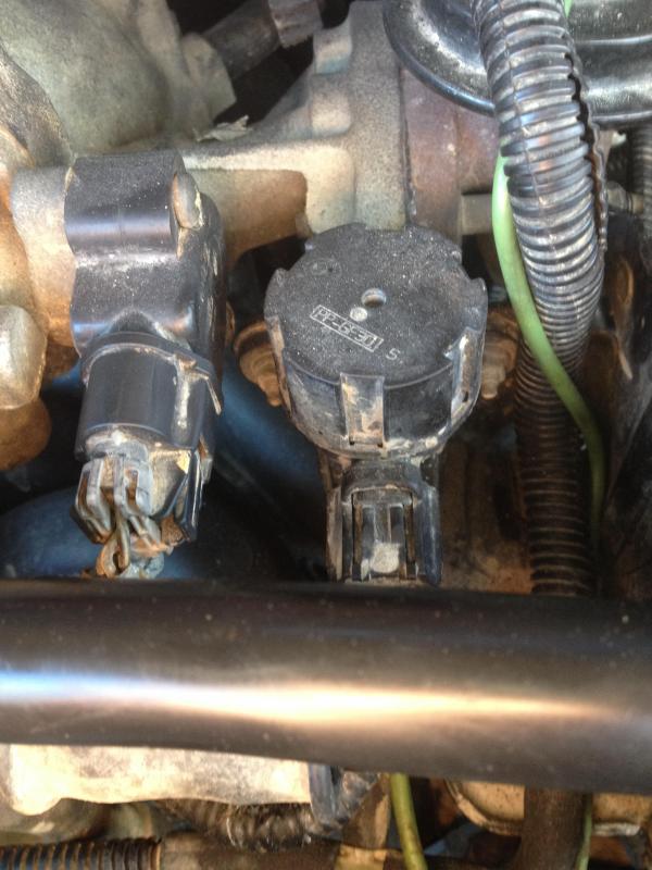
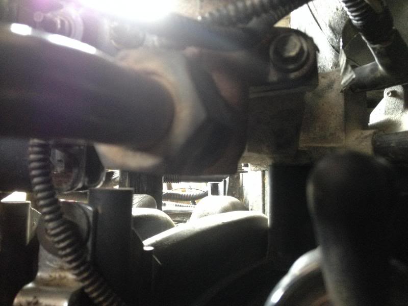
19) Remove EGR valve-to- exhaust – manifold pipe.
a) It is easiest to remove the one 8mm bolt and (8mm nut/stud) to separate the EGR valve from the exhaust manifold. See pictures for reference. You will need a replacement gasket for this as well.

15) Remove the connectors to the COPS/Ignition coils.
a)Use a 7mm socket and long extension to remove all 8 bolts retain the COP (Coil over plugs).

b) Once the bolts are removed disconnect the electrical connector and pull the coils of each cylinder and set them aside. (Check for residue and resistance on the ignition coils.


16) Romove the IAC hose
This hose is connected to the very back of the throttle body and is obviously attached to top line on the intake.
See the overview section above:
17) Remove the DPFT(Differential feedback transducer), connector and hoses.
a) this is held on by two 8-mm nuts, remove the nuts and label the connector and two small hoses at the bottom.

18) Remove engine vacuum regulator sensor.
The connector on the right.

19) Remove EGR valve-to- exhaust – manifold pipe.
a) It is easiest to remove the one 8mm bolt and (8mm nut/stud) to separate the EGR valve from the exhaust manifold. See pictures for reference. You will need a replacement gasket for this as well.


 01-29-2014, 03:52 PM
#5
20) Disconnect the + lead on the alternator and the voltage regulator.
a) This simply contains a nut that holds the +(positive lead) from the alt to the starter relay. Remove the nut and remove the large wire from the alt.
b) Now remove the voltage regulator/sensor connector at the top of the alt. and label it.
21) Remove the bolts holding the alternator to the block and remove the bracket to the intake manifold.
a) The main bolts (two) are 10mm and disconnect the alt from the enginge. However, the crossover has a bracket with one bolt helping support the top of the alt. Remove that bracket or bolt to remove the alt. from the engine bay.
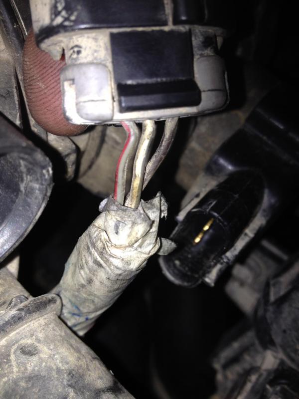
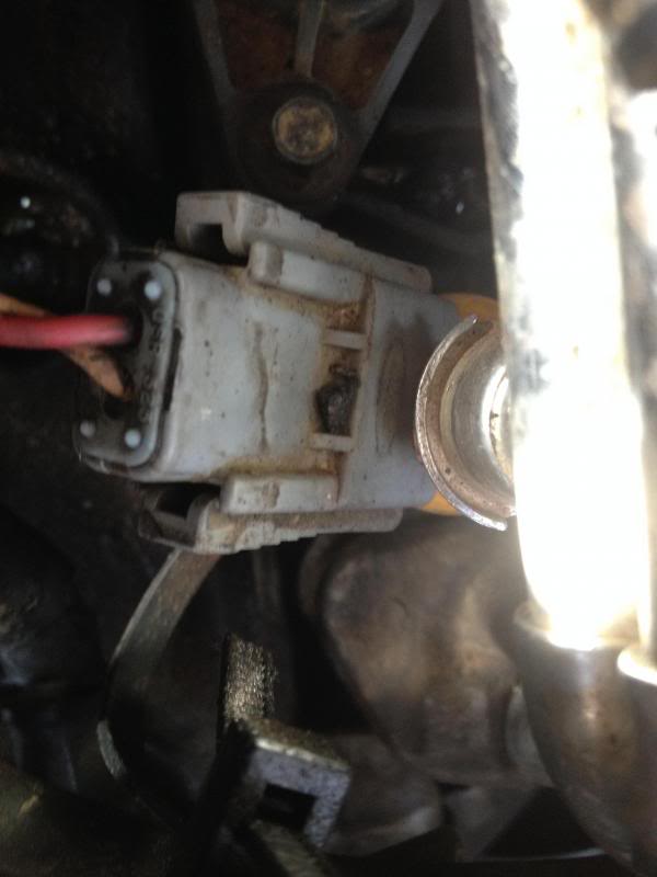
22) Disconnect the electrical connectors for the Camshaft Sensor, Coolant Temp, and Idle speed control solenoid. Label each appropriately
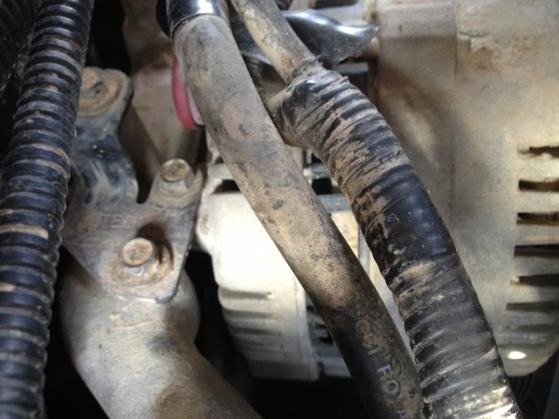
23) Disconnect the heater hose.
a) Use pliers or other means to disconnect the heater core hose from the crossover. See picture:
24) If necessary unbolt the power steering reservoir from the bottom of the engine to move it even further out of the way.
25) Brake Booster Bracket/hose removal.
See overview for more details:

26) Loosening intake manifold bolts.
a)You want to loosen these bolts in �-turns increments opposite of the tightening sequence. See pic for reference. There are 10 in total. You will need a long extension for this.
27) Lifting the Intake manifold from the cylinder headers.
1) Disconnect the intake manifold tuning valve from the lower plenum.
2) If the manifold is stuck use a little pressure to lift it up. Make sure all bolts are out and to not scare the heads.
28) Removing intake manifold gaskets.
1) Pull or pry the gaskets up and clean all traces of sealant or oil from the surfaces of the cylinder heads and intake manifold.
a) This simply contains a nut that holds the +(positive lead) from the alt to the starter relay. Remove the nut and remove the large wire from the alt.
b) Now remove the voltage regulator/sensor connector at the top of the alt. and label it.
21) Remove the bolts holding the alternator to the block and remove the bracket to the intake manifold.
a) The main bolts (two) are 10mm and disconnect the alt from the enginge. However, the crossover has a bracket with one bolt helping support the top of the alt. Remove that bracket or bolt to remove the alt. from the engine bay.

22) Disconnect the electrical connectors for the Camshaft Sensor, Coolant Temp, and Idle speed control solenoid. Label each appropriately
23) Disconnect the heater hose.
a) Use pliers or other means to disconnect the heater core hose from the crossover. See picture:

24) If necessary unbolt the power steering reservoir from the bottom of the engine to move it even further out of the way.

25) Brake Booster Bracket/hose removal.
See overview for more details:
26) Loosening intake manifold bolts.
a)You want to loosen these bolts in �-turns increments opposite of the tightening sequence. See pic for reference. There are 10 in total. You will need a long extension for this.
27) Lifting the Intake manifold from the cylinder headers.
1) Disconnect the intake manifold tuning valve from the lower plenum.
2) If the manifold is stuck use a little pressure to lift it up. Make sure all bolts are out and to not scare the heads.
28) Removing intake manifold gaskets.
1) Pull or pry the gaskets up and clean all traces of sealant or oil from the surfaces of the cylinder heads and intake manifold.


