Relocating FPDM
 05-26-2014, 08:46 PM
#1
Senior Member
Thread Starter

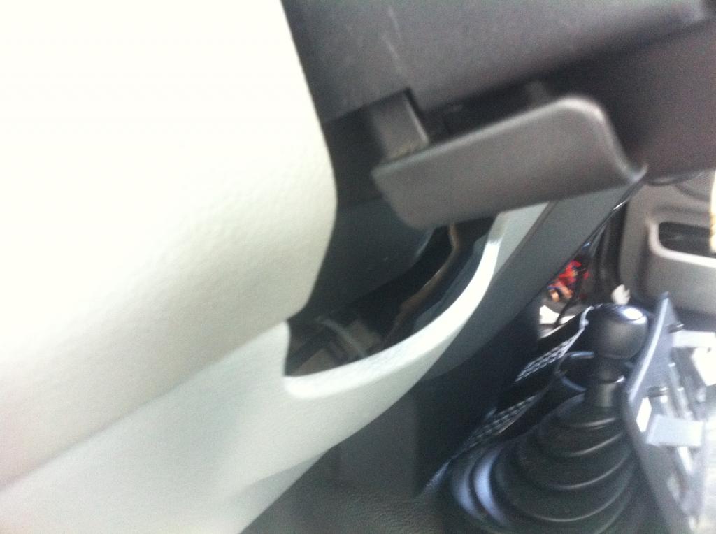
After reading so many FPDM horror stories, I decided to check the one on my truck. Sure enough, the housing was corroded and cracked. Instead of replacing it, I decided to relocate it to the interior. I chose to mount it beneath the steering column:
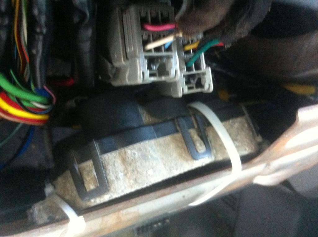
To begin, I looked up a wiring diagram for the FPDM. It has six wires
� White = Power from the inertia cutoff switch
� Black/yellow stripe � Ground
� Pink/black stripe = pump wire #1
� Brown/white stripe � pump wire #2
� Orange � PCM signal wire #1
� Light blue/orange stripe = PCM signal wire #2
Three of these wires can be found in the driver�s side wire channel. These are the heavy gauge white wire and the thinner orange and light blue/orange wires. I cut these wires and extended them to the area beneath the steering column. Note: all connections made in this project were soldered, then covered in heat shrink tubing and electrical tape. Furthermore, I used copper wire that had a similar diameter to those that I extended. To be sure I found the correct wires, I checked them with a multimeter in continuity mode with the pins on the FPDM connector.
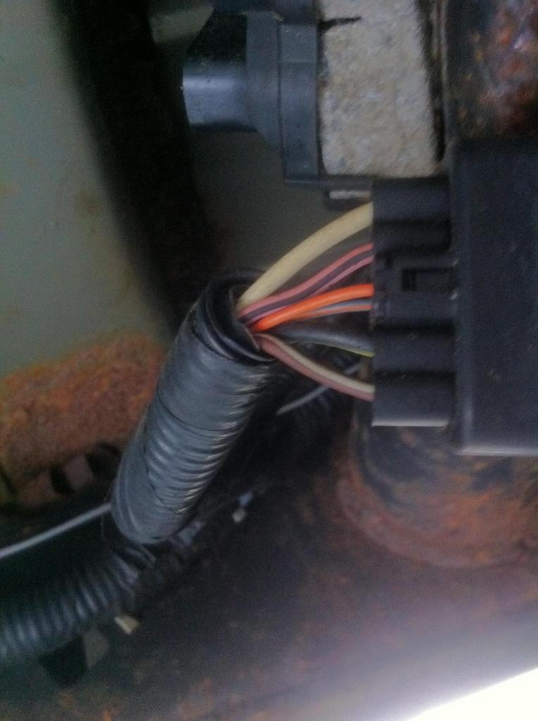
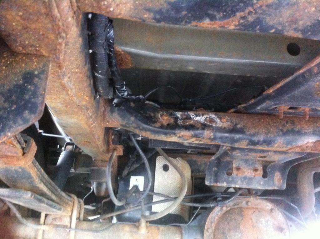
Next, I cut the FPDM connector off from beneath truck. The two pump wires had to be extended to the interior of the truck. I ended up soldering one of the pump wires to the heavy gauge white wire that I cut previously. I ran a separate wire from the cab and soldered it to the second pump wire.
You will notice that the ground wire is attached to a bare silver wire. This wire is used to ground the shielding in the harness. I soldered this wire to the short length of the black/yellow wire that remained after cutting off the connector. I then covered the bare wire with electrical tape.
Finally, I grounded the FPDM to the cab using a crimp-style eyelet.
Overall, this project took me about a day, as it took me a while to run the second pump wire to the back of the truck and wrap it wiring conduit. With the trim panel in place, the FPDM can hardly be seen:

To begin, I looked up a wiring diagram for the FPDM. It has six wires

� White = Power from the inertia cutoff switch
� Black/yellow stripe � Ground
� Pink/black stripe = pump wire #1
� Brown/white stripe � pump wire #2
� Orange � PCM signal wire #1
� Light blue/orange stripe = PCM signal wire #2
Three of these wires can be found in the driver�s side wire channel. These are the heavy gauge white wire and the thinner orange and light blue/orange wires. I cut these wires and extended them to the area beneath the steering column. Note: all connections made in this project were soldered, then covered in heat shrink tubing and electrical tape. Furthermore, I used copper wire that had a similar diameter to those that I extended. To be sure I found the correct wires, I checked them with a multimeter in continuity mode with the pins on the FPDM connector.
Next, I cut the FPDM connector off from beneath truck. The two pump wires had to be extended to the interior of the truck. I ended up soldering one of the pump wires to the heavy gauge white wire that I cut previously. I ran a separate wire from the cab and soldered it to the second pump wire.
You will notice that the ground wire is attached to a bare silver wire. This wire is used to ground the shielding in the harness. I soldered this wire to the short length of the black/yellow wire that remained after cutting off the connector. I then covered the bare wire with electrical tape.

Finally, I grounded the FPDM to the cab using a crimp-style eyelet.
Overall, this project took me about a day, as it took me a while to run the second pump wire to the back of the truck and wrap it wiring conduit. With the trim panel in place, the FPDM can hardly be seen:

 05-26-2014, 09:31 PM
#2
Well dang.....i just bought the new one with stand offs and called it a day.....good job
05-27-2014, 07:00 AM
#3
Mark
iTrader: (1)
yea...think I will just spend the $50 when mine starts looking bad...

The following users liked this post:
techrep (05-27-2014)