How to Install Automatic Air in Your F150
 05-30-2013, 07:46 PM
#1


So I have yet to see a how to write up on this and since I have successfully completed the process (well mostly successfully I still have to get some of the components permanently mounted) I thought I would share how.
I did most of the work a few months ago and between now and then I lost my phone in a drinking mishap and I am in the hospital now so I may not be able to provide detailed close-ups of areas that people might have questions. As soon as I get out of the hospital I will be more than happy to try and get some specific pics to answer any questions people have. Just be patient with me.
Ok first the items that you will need:
1. Electronic blower motor speed controller. It looks like this https://www.f150forum.com/attachment...switch-012.jpg
2. EATC Control Module-
3. Lariat Radio bezel from a console shifted lariat-
4. Interior temperature sensor from a lariat or fx4 with auto air-
5. Lariat/Mark LT/ or FX4 (has to come from an FX4 with EATC not any FX4 cluster will work) Speedo Cluster.
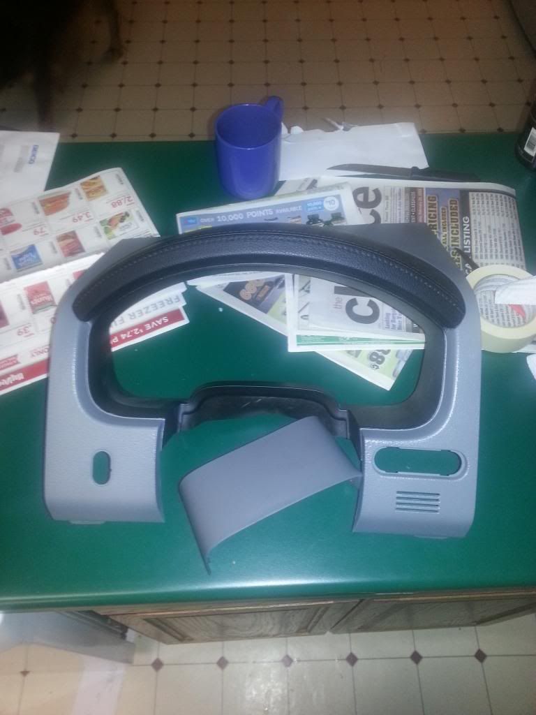
6. Speedo cover Bezel from Lariat/LT/ or FX4 (again needs to come from Fx4 with the proper air package) you may have to paint it to match your interior like I did.
6. Wiring and Soldering equipment, Spare wire, shrink wrap, voltmeter ETC. I suggest that for all the electronic bits that that even if you buy them new from for that you cruise junkyards and pick and pulls and get them to cut all the connectors with pigtails for these parts from a donor vehicle, it makes it easier to get a good connection.
That�s all I can remember for the moment off the top of my head. This process is a little involved and I recommend you be a little confident with your ability to locate wires in your stock wiring and cut and resolder them safely before attempting this.
Ok so let�s start at the speedometer and work our way across the dash.
1. Remove the stock speedo bezel, speedometer, and steering wheel (if you feel you need to, I personally just worked around it)
Let me take a moment to explain why you have to change the speedo for this. Unfortunately the EMTC and EATC modules tell the PCM to activate the AC clutch in two different ways. The EMTC connects to a violet hot wire coming off the speedo that grounds at the unit when you hit the AC button. The EATC communicates on a data line that ironically is the same color violet. The Data line exists in the XLT and FX4 (Non EATC equipped) clusters but unfortunately the microprocessor it talks to is not programmed to translate the signal. That is why you have to install an EATC cluster. I have read rumors that ford can reprogram the Microprocessor in the XLT cluster, however do that at your own risk I called about 4 Ford service departments and explained my projects and none seemed to be confident they could do it properly. So you are welcome to try and save money and do it that way.
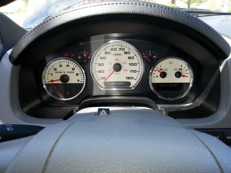
2. Install the new cluster. If you went FX4 (good luck finding one that for sure came with EATC) then it is a simple plug and play operation. You will need to find a cover for the for the trip/reset/info buttons. If you do a Mark LT/Lariat Speedo then you will want to get a pre-06 or older cluster if you can so that you can avoid the TPMS fault (I didn�t know this till after the fact and now it�s pretty annoying to have to clear that out every time I start the truck) If you want the buttons to work you will need to follow this write up I made:
https://www.f150forum.com/f4/how-ins...r-work-208772/
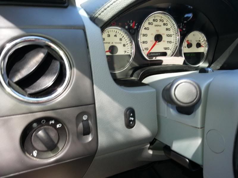
3. Install the In vehicle temperature sensor. If you look to the right of the steering column (while facing from the driver seat) you will see a rectangular hole.
Ok this is a bad pic because I was taking a picture of the Info center and it is blocking the rectangular piece but it is where the arrow is pointing.
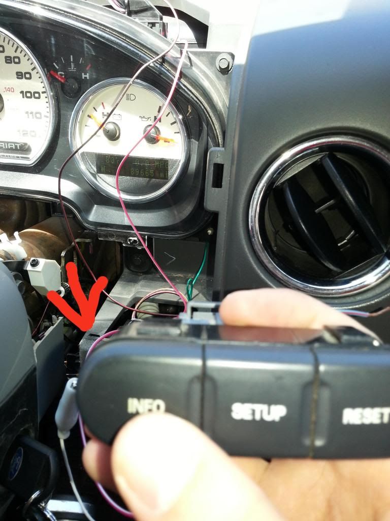
This rectangular cut out is made to accept the rectangular side of the in vehicle temp sensor. You will need to find some bolts or self-taping screws to hold it in place.
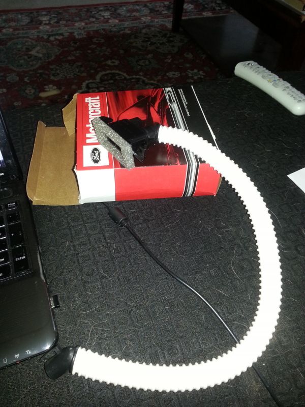
Once the rectangular side is mounted you are going to run the white tube under your dash to just above the driver's side floor air vent. If you look at the side of the air box above the vent you will see a circular piece sticking down from the corner on the right side.
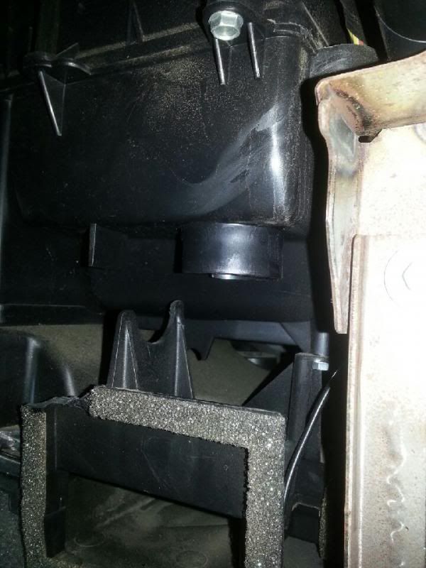
If you get a light and look on the underside of that you will actually see something that says remove for EATC or something like that. If you can get a hole saw in this part cut out the underside of that circular piece and install the tube in the hole. I couldn�t so I went at it from the side. If you do that though I discovered that you have to get creative and figure out how to hook it to a 90 degree elbow joint. This is because the air has to flow across the opening within the air box without an elbow the air will flow into the tube and make a mini vent. This is one of the things I was referring to when I said that I wasn't 100 % done on the final placement of everything.
I did most of the work a few months ago and between now and then I lost my phone in a drinking mishap
and I am in the hospital now so I may not be able to provide detailed close-ups of areas that people might have questions. As soon as I get out of the hospital I will be more than happy to try and get some specific pics to answer any questions people have. Just be patient with me.Ok first the items that you will need:
1. Electronic blower motor speed controller. It looks like this https://www.f150forum.com/attachment...switch-012.jpg
2. EATC Control Module-

3. Lariat Radio bezel from a console shifted lariat-

4. Interior temperature sensor from a lariat or fx4 with auto air-

5. Lariat/Mark LT/ or FX4 (has to come from an FX4 with EATC not any FX4 cluster will work) Speedo Cluster.
6. Speedo cover Bezel from Lariat/LT/ or FX4 (again needs to come from Fx4 with the proper air package) you may have to paint it to match your interior like I did.

6. Wiring and Soldering equipment, Spare wire, shrink wrap, voltmeter ETC. I suggest that for all the electronic bits that that even if you buy them new from for that you cruise junkyards and pick and pulls and get them to cut all the connectors with pigtails for these parts from a donor vehicle, it makes it easier to get a good connection.
That�s all I can remember for the moment off the top of my head. This process is a little involved and I recommend you be a little confident with your ability to locate wires in your stock wiring and cut and resolder them safely before attempting this.
Ok so let�s start at the speedometer and work our way across the dash.
1. Remove the stock speedo bezel, speedometer, and steering wheel (if you feel you need to, I personally just worked around it)
Let me take a moment to explain why you have to change the speedo for this. Unfortunately the EMTC and EATC modules tell the PCM to activate the AC clutch in two different ways. The EMTC connects to a violet hot wire coming off the speedo that grounds at the unit when you hit the AC button. The EATC communicates on a data line that ironically is the same color violet. The Data line exists in the XLT and FX4 (Non EATC equipped) clusters but unfortunately the microprocessor it talks to is not programmed to translate the signal. That is why you have to install an EATC cluster. I have read rumors that ford can reprogram the Microprocessor in the XLT cluster, however do that at your own risk I called about 4 Ford service departments and explained my projects and none seemed to be confident they could do it properly. So you are welcome to try and save money and do it that way.
2. Install the new cluster. If you went FX4 (good luck finding one that for sure came with EATC) then it is a simple plug and play operation. You will need to find a cover for the for the trip/reset/info buttons. If you do a Mark LT/Lariat Speedo then you will want to get a pre-06 or older cluster if you can so that you can avoid the TPMS fault (I didn�t know this till after the fact and now it�s pretty annoying to have to clear that out every time I start the truck) If you want the buttons to work you will need to follow this write up I made:
https://www.f150forum.com/f4/how-ins...r-work-208772/
3. Install the In vehicle temperature sensor. If you look to the right of the steering column (while facing from the driver seat) you will see a rectangular hole.
Ok this is a bad pic because I was taking a picture of the Info center and it is blocking the rectangular piece but it is where the arrow is pointing.

This rectangular cut out is made to accept the rectangular side of the in vehicle temp sensor. You will need to find some bolts or self-taping screws to hold it in place.
Once the rectangular side is mounted you are going to run the white tube under your dash to just above the driver's side floor air vent. If you look at the side of the air box above the vent you will see a circular piece sticking down from the corner on the right side.

If you get a light and look on the underside of that you will actually see something that says remove for EATC or something like that. If you can get a hole saw in this part cut out the underside of that circular piece and install the tube in the hole. I couldn�t so I went at it from the side. If you do that though I discovered that you have to get creative and figure out how to hook it to a 90 degree elbow joint. This is because the air has to flow across the opening within the air box without an elbow the air will flow into the tube and make a mini vent. This is one of the things I was referring to when I said that I wasn't 100 % done on the final placement of everything.
Last edited by Thisguyuknow; 05-30-2013 at 11:56 PM.

The following users liked this post:
Ford4x4LIFE (06-02-2013)
05-30-2013, 07:47 PM
#2
Here is an artistic drawing of how the tube will look in the box.
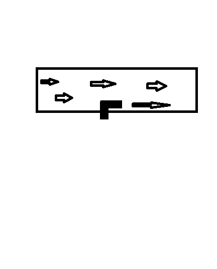
Be creative with the mounting of the tube. If you did it right you should not feel air flowing out of the Temp sensor when you turn the air to high. Air should flow from the cab into the sensor when the air speed is up.
Next (assuming that you got the pigtail for this sensor) there will be two wires on the plug, PK/BK and WT/OG. These will run to the back of the EATC module so for now just extend the wires as needed to reach and tuck them where you can access them when you remove the radio bezel.
4. According to the wiring diagram the EATC uses an input from the Auto lamp/unload sensor. Why I have no idea. Maybe someone else here knows. I acquired a sensor from a lariat model complete with the pigtail and I discovered 2 things first it is identical to the XLT one same number of pins and everything and two the lariat pigtail for this sensor is missing the wire referred to in the diagram. But the pin on the sensor does exist. So my assumption is that probably the actually setup piggy backs off of something else. To be on the safe side what I did was I stripped the end of a small gauge wire and slid it into the pin hole for pin 1 (which is the pin used by the EATC according to the diagram) if you look on the connector the pins should be numbered with a 1 on one end and then whatever the last number is on the other... I wish I had a pic of this but I don't sorry guys and gals. If you look at the info center button link I added earlier it is very similar how I added to the two wires to that. Make sure to use a large enough wire to reach the back of the EATC and run it with the two wires from the temp sensors.
5. Now we are going to do some editing to the stock harness to get ready.
Ok so the last wiring change will do on this side of the dash involves the violet wires I mentioned earlier.
Here is the best screenshot I could get of the wiring for the cluster.
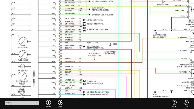
Ok When facing the cluster from the seat there are 2 connectors at the top of the speedo. C220A is on your left and is larger C220B is on the right and has about half as many wires.
On C220B you are looking for the VIO wire in pin 2. If you want to be sure that you have the right one you can remove the shroud like in the pic below using a screw driver and see the pin numbers marked in the plastic.
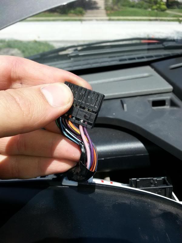
Once you find the right wire. Cut it and tape up the part the runs to C220B. The end that runs into the main harness you will extend it with enough length to reach C220A.
Next, find pin 29 on C220A. Again this is the same color Violet as the wire we just cut out of C220B. Take the wire you extended from pin 2 in C220B and splice it into the VIO wire from pin 29 in C220A. Do not disconnect the end of the wire that runs into the harness. I cut this wire in two stripped the ends put on some shrink tubing, twisted in the Wire from C220B then soldered everything back together and covered with the wrap. You can also use a wiretap if you want but I prefer making the least resistant connection I can.
6. that is it for this portion of the dash. Put everything back together. Install the speedo buttons in the bezel and everything should go back together the way the stock stuff came out.
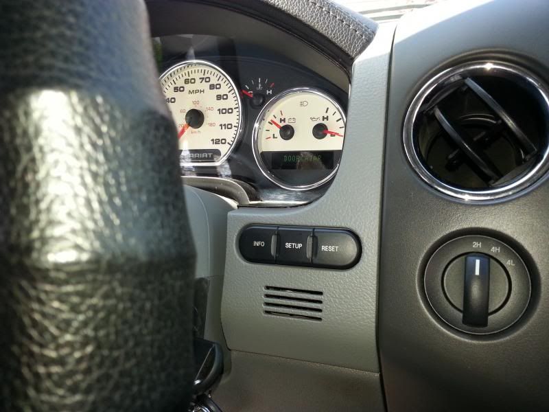
Just Kind of a FYI here. As you can see I have the buttons for the adjustable pedal installed here. I did a complete lariat conversion and that is functional because I added the pedals. If you do not like to have buttons that don't work then I have seen these bezels pop up occasionally on EBay with this hole covered but they are rare. Or if you ever intend to convert to an electric slider rear window this button happens to be the same size and shape as the button for the rear slider. Just food for thought.
Alright now part 2 (so to speak).
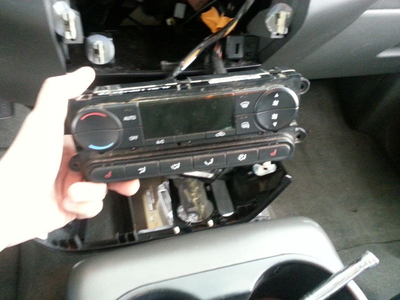
1. Remove the Radio bezel. If you have never done this before it is clipped in you just need to get something thin in between the cracks and pry it gently to get it started. Once it is removed you will need to unplug the airbag light from the top , the two plugs from the EMTC unit, and the cigarette lighter/various other stuff attached to the bezel. Set the Bezel and EMTC aside.
2. Ok so according to the diagrams there may be an issue with early run 2004 rigs because those models had an extra actuator door or something. I’m not too clear on what the issue is but just that it may be a problem so please check to make sure your rig doesn’t have this cause youll be dead in the water.
Both the EMTC and EATC module have two connectors on the rear. On the EMTC you just removed, the right side connector (when facing from the seat) is C294A. The bulky one on the left which has 4 wires is C294B. IF you are looking at the EATC from the same perspective the Right connector is C228A and the smaller white one on the left is C228B.
C294A and C228A are actually identical. Both have the same pinout and electrically all the door actuators are the same so plug C294A into the C228A Slot.

Be creative with the mounting of the tube. If you did it right you should not feel air flowing out of the Temp sensor when you turn the air to high. Air should flow from the cab into the sensor when the air speed is up.
Next (assuming that you got the pigtail for this sensor) there will be two wires on the plug, PK/BK and WT/OG. These will run to the back of the EATC module so for now just extend the wires as needed to reach and tuck them where you can access them when you remove the radio bezel.
4. According to the wiring diagram the EATC uses an input from the Auto lamp/unload sensor. Why I have no idea. Maybe someone else here knows. I acquired a sensor from a lariat model complete with the pigtail and I discovered 2 things first it is identical to the XLT one same number of pins and everything and two the lariat pigtail for this sensor is missing the wire referred to in the diagram. But the pin on the sensor does exist. So my assumption is that probably the actually setup piggy backs off of something else. To be on the safe side what I did was I stripped the end of a small gauge wire and slid it into the pin hole for pin 1 (which is the pin used by the EATC according to the diagram) if you look on the connector the pins should be numbered with a 1 on one end and then whatever the last number is on the other... I wish I had a pic of this but I don't sorry guys and gals. If you look at the info center button link I added earlier it is very similar how I added to the two wires to that. Make sure to use a large enough wire to reach the back of the EATC and run it with the two wires from the temp sensors.
5. Now we are going to do some editing to the stock harness to get ready.
Ok so the last wiring change will do on this side of the dash involves the violet wires I mentioned earlier.
Here is the best screenshot I could get of the wiring for the cluster.

Ok When facing the cluster from the seat there are 2 connectors at the top of the speedo. C220A is on your left and is larger C220B is on the right and has about half as many wires.
On C220B you are looking for the VIO wire in pin 2. If you want to be sure that you have the right one you can remove the shroud like in the pic below using a screw driver and see the pin numbers marked in the plastic.

Once you find the right wire. Cut it and tape up the part the runs to C220B. The end that runs into the main harness you will extend it with enough length to reach C220A.
Next, find pin 29 on C220A. Again this is the same color Violet as the wire we just cut out of C220B. Take the wire you extended from pin 2 in C220B and splice it into the VIO wire from pin 29 in C220A. Do not disconnect the end of the wire that runs into the harness. I cut this wire in two stripped the ends put on some shrink tubing, twisted in the Wire from C220B then soldered everything back together and covered with the wrap. You can also use a wiretap if you want but I prefer making the least resistant connection I can.
6. that is it for this portion of the dash. Put everything back together. Install the speedo buttons in the bezel and everything should go back together the way the stock stuff came out.


Just Kind of a FYI here. As you can see I have the buttons for the adjustable pedal installed here. I did a complete lariat conversion and that is functional because I added the pedals. If you do not like to have buttons that don't work then I have seen these bezels pop up occasionally on EBay with this hole covered but they are rare. Or if you ever intend to convert to an electric slider rear window this button happens to be the same size and shape as the button for the rear slider. Just food for thought.
Alright now part 2 (so to speak).
1. Remove the Radio bezel. If you have never done this before it is clipped in you just need to get something thin in between the cracks and pry it gently to get it started. Once it is removed you will need to unplug the airbag light from the top , the two plugs from the EMTC unit, and the cigarette lighter/various other stuff attached to the bezel. Set the Bezel and EMTC aside.
2. Ok so according to the diagrams there may be an issue with early run 2004 rigs because those models had an extra actuator door or something. I’m not too clear on what the issue is but just that it may be a problem so please check to make sure your rig doesn’t have this cause youll be dead in the water.
Both the EMTC and EATC module have two connectors on the rear. On the EMTC you just removed, the right side connector (when facing from the seat) is C294A. The bulky one on the left which has 4 wires is C294B. IF you are looking at the EATC from the same perspective the Right connector is C228A and the smaller white one on the left is C228B.
C294A and C228A are actually identical. Both have the same pinout and electrically all the door actuators are the same so plug C294A into the C228A Slot.
Last edited by Thisguyuknow; 05-30-2013 at 08:36 PM.
05-30-2013, 07:48 PM
#3
Here is a shot of C294A plugged into the EATC
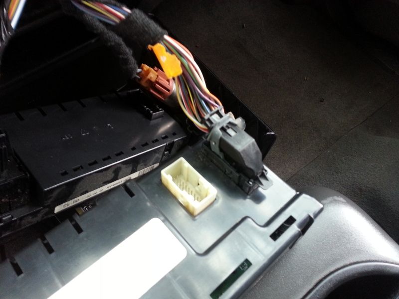
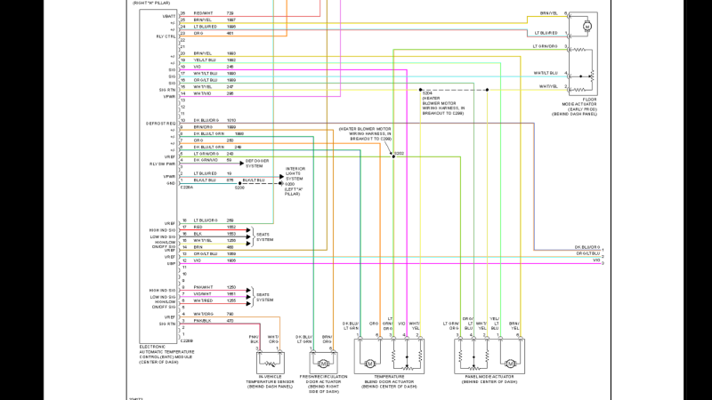
Here is a screen shot of the EATC Wiring.
Now we need to locate the AC request wire in plug C294A. Warning here there are 2 violet wires in this plug so it is important you find the correct one! The correct VIO wire is in Pin 2 on the connector and the incorrect one is in pin 18. I highly suggest that you remove the shroud on the connector and check the pin out numbers stamped in the plastic. You can also use a volt meter but it is just easier to manually count it out.
Here is a pic I took of C294A after cutting the mentioned VIO wire out of it.
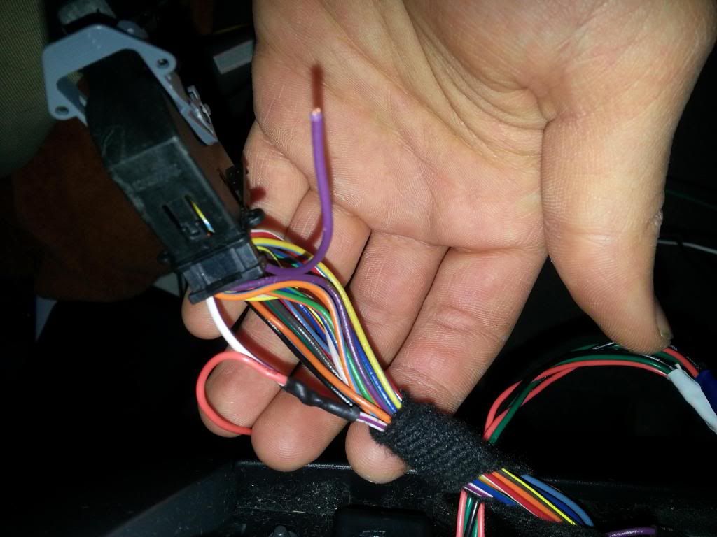
Once you have interrogated the violet wires and determined the correct one (hopefully). Cut the wire and tape off the side that runs to C294A. You will need to make sure that you at least get connector C228B from a part out because there are too many small connectors to try and make it work without the correct plug. C228B is the white connector to the left of the slot that C294A from the original harness plugs into. Locate the VT wire in C228B and splice it to the Violet wire you just removed from C294A. There is only one VT wire in C228B but if you want to double check yourself (always a good idea to do) it should be in pin 12. Just a quick FYI this is the other end of the VIO wire you relocated at the speedo.
Next take the Wire that you ran from the Auto lamp/Sun load Sensor and splice it to BRN in C228B. This is the only BRN wire but again if you want to double check it, the pin number is 14. Then Take the two wires from in vehicle temp sensor and connect them to their respective colors in C228B (PNK/BK to PNK/BK and WHT/OG to WHT/OG)
This is a pic of C228B
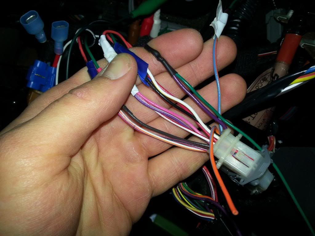
The following wires are located in C228B that you will need to tape up and ignore(Unless you are swapping in Lariat heated seats as well) Rd,BK,WHT/YL,PNK/WHT,VIO/WHT,WHT/RD these are located in pins, 6,7,8,15,16,17.
Do the same as the wires in the previous paragraph with the ORG/LT BLU wire in pin 13. This wire is for the steering column controls which is a cool idea and all but screw that. If you ever feel like swapping on the fancy steering wheel with the extra buttons (which I have no idea if it is possible) you will need this wire to get the controls on the wheel to work the Air.
The final wire left in C228B should be Lt Blu/OG in pin 18. Again I am doing this from memory and am in the hospital so I can’t remember the gauge wire you need for this but if you look at the pigtail from the Blower motor Speed controller make sure it is a similar gauge to the LtBlu/ OG wire on that connector. You must extend this wire with enough length to reach the passenger side of the air box where the blower motor is. This is between the Fuse box and the right side of the air box (when facing the air box from the seat) Run this wire through the dash however you want and make sure you get it to somewhere you can reach it when we get part 3 and remove the glove box.
This is all that there is to do in the center part of the dash. Plug C294A and C228B into the EATC Module, plug in your cig lighter/accessories, and your seatbelt warning light into the new radio bezel and close it all back up
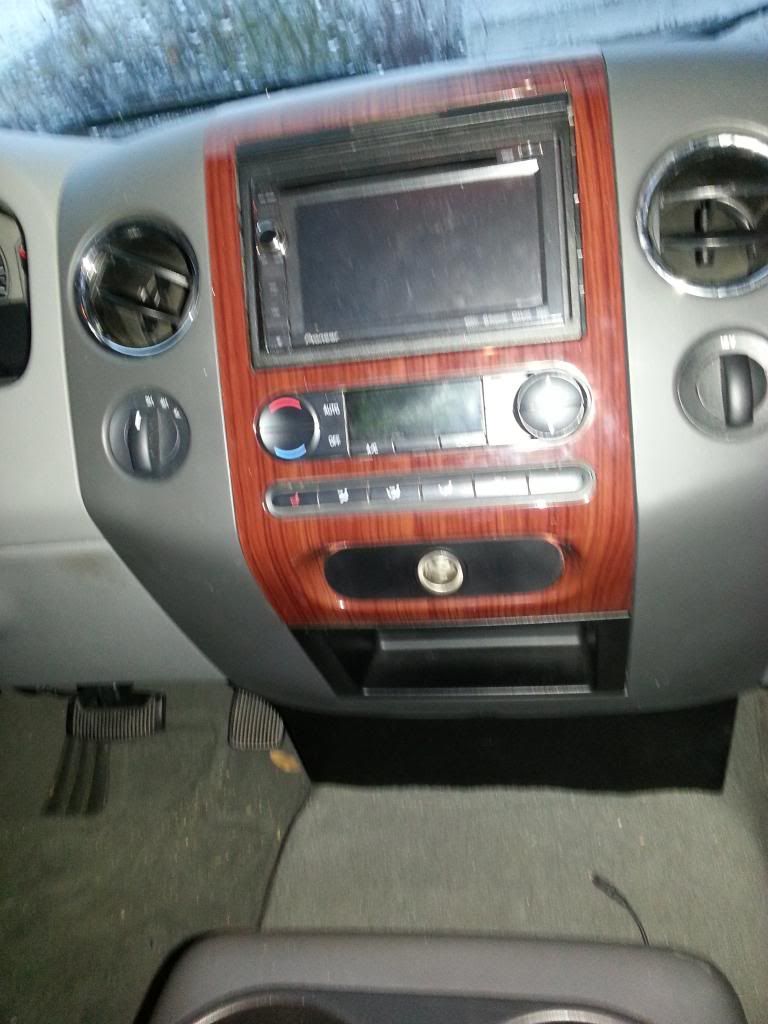
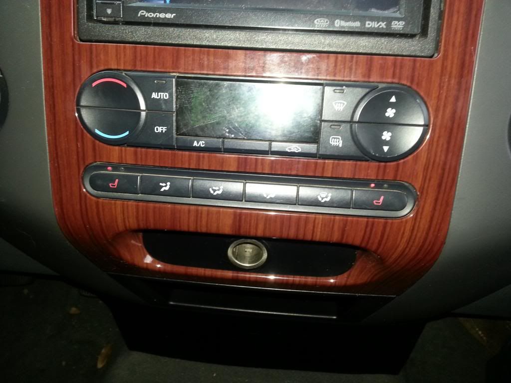
Now I am not a huge fan of wood so this isn’t exactly the most Ideal look but unfortunately this is the only option as no Fx4s with the EATC come with a column shift, at least that I have seen as of yet. Maybe this can be cleanly painted in a way that doesn’t look bad, I don’t know. I didn’t want to risk rattle canning the bezel black since although not impossible to find these lariat radio bezels are a little rare to come by.

Here is a screen shot of the EATC Wiring.

Now we need to locate the AC request wire in plug C294A. Warning here there are 2 violet wires in this plug so it is important you find the correct one! The correct VIO wire is in Pin 2 on the connector and the incorrect one is in pin 18. I highly suggest that you remove the shroud on the connector and check the pin out numbers stamped in the plastic. You can also use a volt meter but it is just easier to manually count it out.
Here is a pic I took of C294A after cutting the mentioned VIO wire out of it.

Once you have interrogated the violet wires and determined the correct one (hopefully). Cut the wire and tape off the side that runs to C294A. You will need to make sure that you at least get connector C228B from a part out because there are too many small connectors to try and make it work without the correct plug. C228B is the white connector to the left of the slot that C294A from the original harness plugs into. Locate the VT wire in C228B and splice it to the Violet wire you just removed from C294A. There is only one VT wire in C228B but if you want to double check yourself (always a good idea to do) it should be in pin 12. Just a quick FYI this is the other end of the VIO wire you relocated at the speedo.
Next take the Wire that you ran from the Auto lamp/Sun load Sensor and splice it to BRN in C228B. This is the only BRN wire but again if you want to double check it, the pin number is 14. Then Take the two wires from in vehicle temp sensor and connect them to their respective colors in C228B (PNK/BK to PNK/BK and WHT/OG to WHT/OG)
This is a pic of C228B

The following wires are located in C228B that you will need to tape up and ignore(Unless you are swapping in Lariat heated seats as well) Rd,BK,WHT/YL,PNK/WHT,VIO/WHT,WHT/RD these are located in pins, 6,7,8,15,16,17.
Do the same as the wires in the previous paragraph with the ORG/LT BLU wire in pin 13. This wire is for the steering column controls which is a cool idea and all but screw that. If you ever feel like swapping on the fancy steering wheel with the extra buttons (which I have no idea if it is possible) you will need this wire to get the controls on the wheel to work the Air.
The final wire left in C228B should be Lt Blu/OG in pin 18. Again I am doing this from memory and am in the hospital so I can’t remember the gauge wire you need for this but if you look at the pigtail from the Blower motor Speed controller make sure it is a similar gauge to the LtBlu/ OG wire on that connector. You must extend this wire with enough length to reach the passenger side of the air box where the blower motor is. This is between the Fuse box and the right side of the air box (when facing the air box from the seat) Run this wire through the dash however you want and make sure you get it to somewhere you can reach it when we get part 3 and remove the glove box.
This is all that there is to do in the center part of the dash. Plug C294A and C228B into the EATC Module, plug in your cig lighter/accessories, and your seatbelt warning light into the new radio bezel and close it all back up
Now I am not a huge fan of wood so this isn’t exactly the most Ideal look but unfortunately this is the only option as no Fx4s with the EATC come with a column shift, at least that I have seen as of yet. Maybe this can be cleanly painted in a way that doesn’t look bad, I don’t know. I didn’t want to risk rattle canning the bezel black since although not impossible to find these lariat radio bezels are a little rare to come by.

Last edited by Thisguyuknow; 05-30-2013 at 10:15 PM.
05-30-2013, 07:49 PM
#4
Alrighty Part 3. Almost done.
1. Remove the Glove box. There is a rubber stopper on the side of the box by the outside wall, push in and the box should fold out. Then remove the bolts from the bottom of the door and the whole thing should move out of your way.
2. Once the glove box is out of the way, locate the plug that connects to the original Blower Motor Resistor and unplug it. I left the old Resistor in place to plug the hole in the air box.
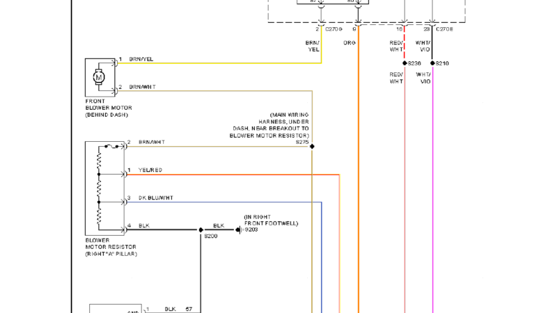
Alright this next part is a tad involved so please take a close look at the diagrams below showing the two different blower controller set ups.
This is the original Blower resistor set up. I want to make a note of the 2 breakouts shown as diamond looking black dots. One is BK and the other is BRN/WHT. If you notice the end below the break out runs off the bottom of the picture. Those wires are running to the EMTC unit in your original set up. Also notice that the other side of those wires go to the chassis ground and the blower motor directly (respectively) If decide to cut these wires in the following steps (I will give you two options) make sure you figure out which side of the wire runs to the EMTC and which side runs to the two points I mentioned above. If you splice to the EMTC side you will have an open connection and it wont work as the EMTC side of that connector is just hanging loose behind your radio bezel because we replaced it with C228B.
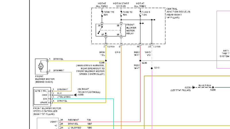
This is the wiring set up for the New blower motor Controller.
3. You need to make a decision on how you want to go about removing the connector for the old blower resistor. I chose to leave the connector in place so that in the unlikely situation any of this needed to be switched back to manual that connector would still be there. Just an easy way to store it I guess. If I could do it again I think I would just completely cut it out of the system. But it is up to you.
Start by cutting the BRN/WHT wire from the connector. If you are leaving the plug in the system make sure that you leave enough slack to splice. If not cut it as close to the plug as you can get. Never hurts to have as much slack as possible. Cutting it close to the plug should avoid the issue of the breakout I mentioned above.
Now cut the BK wire in the same manner.
The remaining 2 wires Yel/Red and DKBlu/WHT are not reused. Just leave them in the plug or cut them out and tape them up depending on how you are handling the original plug issue. Or hook them up to your rocket booster or ejection seat. Whatever you want.
4. Get the connector for the new blower motor speed controller if you haven’t already done so. Try and use the Gauge of the wires in the connectors pig tails as a guide for what size to use when Extending any wires. If the stock wire is reused (such as the ground wire) do not worry if the originally wire is a smaller gauge than what is in the connector to the blower speed controller. I have had mine running this way for almost 6 months ( I installed all the manual air controls from the EATC before winter) and I have not had any wires melt on me yet and my truck remains electrical fire free.(Knock on wood)
Splice the LTBlu/OG wire in pin 3 to the LTBLU/OG wire that you ran from the EATC C228B Pin 18.
Splice BK to BK in the original harness that we cut in step 3. Be mindful of that breakout, it shouldn’t be an issue but double check the ground with a meter or test light to be sure.
Splice BN/WHT from the new connector to the BN/WHT wire that we cut in step 3. Again be mindful of that break out, it should be an issue because cutting close to the old connector should have put us in front of the break out but every truck can be different. We need to ensure that the BN/WHT wire runs directly from the Blower Motor Speed Controller to the Blower motor its self.
The final wire is a little funky. Take a close look at the schematic. The last wire is BRN/Yel. It needs to be spliced into the BRN/YEL wire that runs from the blower motor to the fuse box, so this will be a 3 way splice. You can use either a wiretap, or (my preferred method) cut the brown wire that runs out of the blower motor and solder all three wires together and cover with shrink tubing. Again just use the gauge of the wire on the Blower Motor Speed Controller as a guide if you need to extend the wire. Don’t fret if it is lighter than the BRN/Yel in the original harness, it will be able to handle the current just fine.
Like I mentioned Earlier I left the old Blower motor resistor in place to plug the hole in the box. I have not had an opportunity to mount the Blower Motor Speed Controller Permanently. I plan to cut a hole with a dremmel tool in the air box just below the the resistor. Right now it is just hanging there which is not ideal because it can get hot enough to burn the crap out of someones foot or melt a plastic weather tech liner (both have happened) so I do suggest you get those fins suspended in the air flow of the box ASAP.
1. Remove the Glove box. There is a rubber stopper on the side of the box by the outside wall, push in and the box should fold out. Then remove the bolts from the bottom of the door and the whole thing should move out of your way.
2. Once the glove box is out of the way, locate the plug that connects to the original Blower Motor Resistor and unplug it. I left the old Resistor in place to plug the hole in the air box.
Alright this next part is a tad involved so please take a close look at the diagrams below showing the two different blower controller set ups.
This is the original Blower resistor set up. I want to make a note of the 2 breakouts shown as diamond looking black dots. One is BK and the other is BRN/WHT. If you notice the end below the break out runs off the bottom of the picture. Those wires are running to the EMTC unit in your original set up. Also notice that the other side of those wires go to the chassis ground and the blower motor directly (respectively) If decide to cut these wires in the following steps (I will give you two options) make sure you figure out which side of the wire runs to the EMTC and which side runs to the two points I mentioned above. If you splice to the EMTC side you will have an open connection and it wont work as the EMTC side of that connector is just hanging loose behind your radio bezel because we replaced it with C228B.

This is the wiring set up for the New blower motor Controller.

3. You need to make a decision on how you want to go about removing the connector for the old blower resistor. I chose to leave the connector in place so that in the unlikely situation any of this needed to be switched back to manual that connector would still be there. Just an easy way to store it I guess. If I could do it again I think I would just completely cut it out of the system. But it is up to you.
Start by cutting the BRN/WHT wire from the connector. If you are leaving the plug in the system make sure that you leave enough slack to splice. If not cut it as close to the plug as you can get. Never hurts to have as much slack as possible. Cutting it close to the plug should avoid the issue of the breakout I mentioned above.
Now cut the BK wire in the same manner.
The remaining 2 wires Yel/Red and DKBlu/WHT are not reused. Just leave them in the plug or cut them out and tape them up depending on how you are handling the original plug issue. Or hook them up to your rocket booster or ejection seat. Whatever you want.
4. Get the connector for the new blower motor speed controller if you haven’t already done so. Try and use the Gauge of the wires in the connectors pig tails as a guide for what size to use when Extending any wires. If the stock wire is reused (such as the ground wire) do not worry if the originally wire is a smaller gauge than what is in the connector to the blower speed controller. I have had mine running this way for almost 6 months ( I installed all the manual air controls from the EATC before winter) and I have not had any wires melt on me yet and my truck remains electrical fire free.(Knock on wood)
Splice the LTBlu/OG wire in pin 3 to the LTBLU/OG wire that you ran from the EATC C228B Pin 18.
Splice BK to BK in the original harness that we cut in step 3. Be mindful of that breakout, it shouldn’t be an issue but double check the ground with a meter or test light to be sure.
Splice BN/WHT from the new connector to the BN/WHT wire that we cut in step 3. Again be mindful of that break out, it should be an issue because cutting close to the old connector should have put us in front of the break out but every truck can be different. We need to ensure that the BN/WHT wire runs directly from the Blower Motor Speed Controller to the Blower motor its self.
The final wire is a little funky. Take a close look at the schematic. The last wire is BRN/Yel. It needs to be spliced into the BRN/YEL wire that runs from the blower motor to the fuse box, so this will be a 3 way splice. You can use either a wiretap, or (my preferred method) cut the brown wire that runs out of the blower motor and solder all three wires together and cover with shrink tubing. Again just use the gauge of the wire on the Blower Motor Speed Controller as a guide if you need to extend the wire. Don’t fret if it is lighter than the BRN/Yel in the original harness, it will be able to handle the current just fine.
Like I mentioned Earlier I left the old Blower motor resistor in place to plug the hole in the box. I have not had an opportunity to mount the Blower Motor Speed Controller Permanently. I plan to cut a hole with a dremmel tool in the air box just below the the resistor. Right now it is just hanging there which is not ideal because it can get hot enough to burn the crap out of someones foot or melt a plastic weather tech liner (both have happened) so I do suggest you get those fins suspended in the air flow of the box ASAP.
Last edited by Thisguyuknow; 05-31-2013 at 12:04 AM.
05-30-2013, 07:50 PM
#5
Well that is it. I did that mostly from memory in a hospital bed but that is all the circuits I see in the wiring diagrams that need to be retrofitted so I think I got them all. If I think of anything else I will add them.
I guess it is important to note that this will only work 100 percent properly in an XLT or FX4 model for sure because they are equipped with an exterior temp sensor and the autolamp sensor. The sub xlt models for sure do not have the exterior temp sensor which is used somehow in the AUTO circuit. I see no reason why manually setting the EATC wouldnt work so if for some reason it were still worth it to you to do the job but not get the AUTO feature working 100% properly then go for it. I just can't guarantee this how to for packages that are sub XLT.
Well people have been looking for a complete how to on this and here you go. Feel free to thank me as you feel necessary
Also I have a complete digital shop manual that covers the 06 and 08 years of F150s. The 06 should be good for 04-08s as far as wiring and the 08 should cover any differences that in the last two years (if there are any, I haven't found any yet) Its technically legal to sell these so they are available for free to anyone who wants them and should you happen to donate a dollar or two to my paypal who am I to say no? Anyway I will try to make that available to anyone who wants it.
Enjoy guys and gals, and by all means feel free to comment and ask any questions you have about the process. I just ask that you try to ask your questions in the thread if possible so it doesn't A) flood my inbox and B) if you have a question most likely at least one other person has or will have that same question in the future.
I guess it is important to note that this will only work 100 percent properly in an XLT or FX4 model for sure because they are equipped with an exterior temp sensor and the autolamp sensor. The sub xlt models for sure do not have the exterior temp sensor which is used somehow in the AUTO circuit. I see no reason why manually setting the EATC wouldnt work so if for some reason it were still worth it to you to do the job but not get the AUTO feature working 100% properly then go for it. I just can't guarantee this how to for packages that are sub XLT.
Well people have been looking for a complete how to on this and here you go. Feel free to thank me as you feel necessary
Also I have a complete digital shop manual that covers the 06 and 08 years of F150s. The 06 should be good for 04-08s as far as wiring and the 08 should cover any differences that in the last two years (if there are any, I haven't found any yet) Its technically legal to sell these so they are available for free to anyone who wants them and should you happen to donate a dollar or two to my paypal who am I to say no?
Anyway I will try to make that available to anyone who wants it. Enjoy guys and gals, and by all means feel free to comment and ask any questions you have about the process. I just ask that you try to ask your questions in the thread if possible so it doesn't A) flood my inbox and B) if you have a question most likely at least one other person has or will have that same question in the future.
Last edited by Thisguyuknow; 05-30-2013 at 11:44 PM.
05-30-2013, 07:50 PM
#6
Oh, and I almost forgot, FOR THE LOVE GOD do not tell the Ford parts or service department exactly what you are up to if you choose to buy parts from them. They get real squirrely if they know you are doing an unorthodox modification and get it gets real hard to get the part you need out of them. I suggest you go on ebay and find a lariat that is for sale on Ebay and write down the vin and use that to have them look up parts. Guaranteed if you say you need something like a Blower motor Speed controller from an 06 Lariat they are going to want to get a vin number. And finally to save you time ford cannot order the pigtails for the connectors that you are adding in this swap, you will def need to get them from a part out if you want to hook everything up cleanly.
OK that should be all you need to know!
OK that should be all you need to know!
Last edited by Thisguyuknow; 05-30-2013 at 11:51 PM.

Trending Topics
06-02-2013, 11:56 AM
#8
Senior Member

Good write up man. I've have yet to connect that white plastic cord to the HVAC haha.
I wish you lived in Virginia so you could wire up the Factory OEM Reverse parking aid system that i got. I even got the wiring harness (minus 2 or 3 cables)
I wish you lived in Virginia so you could wire up the Factory OEM Reverse parking aid system that i got. I even got the wiring harness (minus 2 or 3 cables)
06-05-2013, 07:15 AM
#9
You know you should write up your conversion since you went about it a little differently. I wish I had the access you did to junkyards with properly equipped lariats to harvest.