04-08 Odometer Blackout Fix
 01-20-2014, 11:31 AM
#61

Well I finally got my whole dash apart. After pulling out the LCD and replugging it in a few times and placing a thin layer of dielectric grease on the length of each of the pins, I still get nothing. Very frustrating, has anyone tried anything else to get it working? I am wondering if it's something more complicated like that black housing on the actual circuit board, I'm at a loss. The strange thing is I was up in the mountains about a month ago, and overnight it got down to about 5 degrees and when I started up my truck it was completely on, as soon as my truck was warming up it began flashing and then it went off after the truck was warm. A complete piece of **** those dashboards are....
 02-18-2014, 01:24 AM
#62
I've had my odometer going in and out for a few years and last week it went out completely. I found this thread and followed the OPs direction and it worked like a charm! No more intermittent flashing. Also, someone earlier said they were having issues with the doors continually trying to lock themselves while driving - mine was doing the same thing, but since the fix, the door locks have been working perfect as well!
 05-26-2014, 03:51 PM
#64

I bought a used cluster for my wife's '06 Fx4. All the warning lights were going on and off and odometer, compass and thermometer weren't working. I replaced it with a $250 used one. After installing it and disconnecting and reconnecting battery to reset it the truck started and ran fine for 2 weeks. Now it spins over and won't start. I did the battery disconnect/reconnect reset and it worked again. Once. I don't want to have to do that every time. Is there another reset trick I need to know or should I take it apart and hit it with dielectric grease?
Dummy here threw out the old one.
Help!
Thanks,
Clyde
Dummy here threw out the old one.
Help!
Thanks,
Clyde
01-28-2015, 11:52 AM
#66
Junior Member

Join Date: Jan 2013
Posts: 5
Likes: 0
Received 0 Likes
on
0 Posts

Time to add my experience on the Odometer LCD blackout on my 06 SCREW. When I bought the truck 2.5 years ago, the screen was out. I got a good deal on it because of this. I was able to get a Ford dealer to pull the mileage from the OBDII, so I knew what I was getting. I was also aware of the fix for the screen based on this thread.
I was able to get the Odo working using the method described here, only to have it go out again shortly after the truck got warm. I repeated the process a couple of times, cleaning the contacts and adding a thin coat of dielectric grease. It only worked for a short time.
Here is what I did last week which appears to be working:
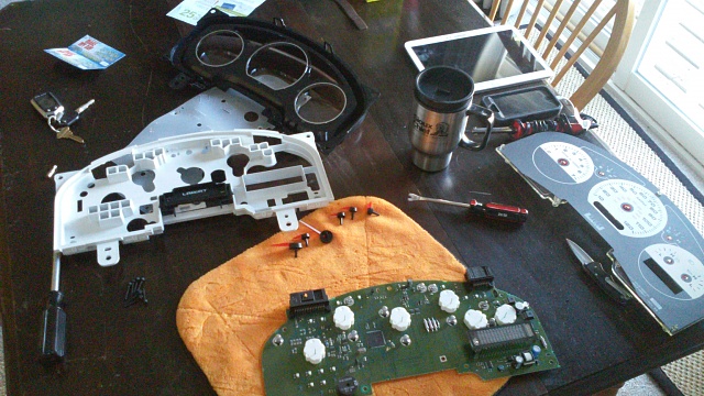
1. Pulled cluster and removed screen from housing and then also removed cluster electronic board from the cluster housing. Remember to mark the locations of the gauge needles.
2. Sprayed Deoxit on the LCD pins as well as the female plug and worked the pins in and out a few times in the hope it would removed any oxidation and restore the connection.
3. Reassemble and test. Still not working. Crap!
4. Removed screen and board from the housing again and then plugged screen and board into the harness without the housing. Now it works, but blinks too much.
5. Put board and LCD back into the housing and try again- Not working.
6. Pulled board and LCD again. Inspected soldering on the female plug. One was suspect, but probably OK. Touched a soldering pen to each of the pins anyway, but did not add any solder.
7. Plugged board and LCD back up without the housing. Works but still blinking. I noticed that if I push back on the top of the LCD screen lightly, the connection was more consistent. Because of the way the LCD fits, I could not do this while the board and LCD were installed in the housing.
8. I then bent the pins so that they were no longer 90 degrees to the screen. Approximately 120 degrees. Sorry, but no pictures. If you picture the screen as it would be mounted in the dash, the pins would be angled down slightly.
9. After I installed the board back on the housing, I first plugged the LCD pins into the female counterpart and then snapped the LCD Screen into place. The result is that the pins push against the contacts a little harder. After reassembly, it it is working again! Time will tell if warmer weather will cause the issue to reappear.
Note: I messed up the position of the fuel gauge and speedo needles in one of my previous attempts to fix. In the final fix, I temporarily left the clear plastic off the cluster and only lightly pushed in the needles. After filling up the truck and using the GPS on my phone to check the speed, I was able to put the pins in the right position.
I was able to get the Odo working using the method described here, only to have it go out again shortly after the truck got warm. I repeated the process a couple of times, cleaning the contacts and adding a thin coat of dielectric grease. It only worked for a short time.
Here is what I did last week which appears to be working:
1. Pulled cluster and removed screen from housing and then also removed cluster electronic board from the cluster housing. Remember to mark the locations of the gauge needles.
2. Sprayed Deoxit on the LCD pins as well as the female plug and worked the pins in and out a few times in the hope it would removed any oxidation and restore the connection.
3. Reassemble and test. Still not working. Crap!
4. Removed screen and board from the housing again and then plugged screen and board into the harness without the housing. Now it works, but blinks too much.
5. Put board and LCD back into the housing and try again- Not working.
6. Pulled board and LCD again. Inspected soldering on the female plug. One was suspect, but probably OK. Touched a soldering pen to each of the pins anyway, but did not add any solder.
7. Plugged board and LCD back up without the housing. Works but still blinking. I noticed that if I push back on the top of the LCD screen lightly, the connection was more consistent. Because of the way the LCD fits, I could not do this while the board and LCD were installed in the housing.
8. I then bent the pins so that they were no longer 90 degrees to the screen. Approximately 120 degrees. Sorry, but no pictures. If you picture the screen as it would be mounted in the dash, the pins would be angled down slightly.
9. After I installed the board back on the housing, I first plugged the LCD pins into the female counterpart and then snapped the LCD Screen into place. The result is that the pins push against the contacts a little harder. After reassembly, it it is working again! Time will tell if warmer weather will cause the issue to reappear.
Note: I messed up the position of the fuel gauge and speedo needles in one of my previous attempts to fix. In the final fix, I temporarily left the clear plastic off the cluster and only lightly pushed in the needles. After filling up the truck and using the GPS on my phone to check the speed, I was able to put the pins in the right position.
06-21-2015, 11:01 PM
#68
Junior Member
Join Date: Jun 2015
Location: Midwest
Posts: 1
Likes: 0
Received 0 Likes
on
0 Posts
So I've done much research on this, and I haven't found anything particular to my situation. I have 2007 F150 Lariat and the cluster is slightly different. I'd first like to thank murf for the great writeup, because I would have stopped at checking the back for bad solder joints and never took the needles and screen off. His help got me past that part, which is kinda scary in itself.
Here's where mine is different from Murf's. Once you get down to the circuit board, the LCD panel is green lighted letters and a black background, and instead of unplugging and cleaning the pins mine has all 40+ pins soldered directly to the board. After I got the needles and screen off I realized this difference and almost packed it up, and started looking for a replacement. A little more searching and I found that a guy with a 2005 Windstar showed off that he had a similar issue with the flickering screen and his fix was a bad resistor solder joint on the circuit board.
Here's my gauge cluster:
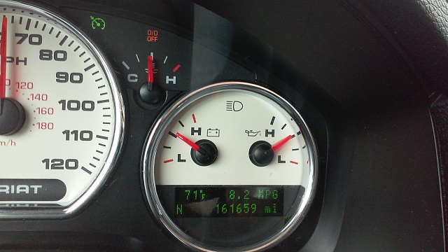
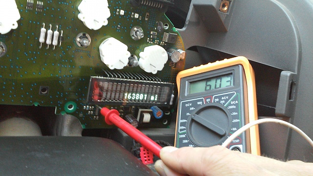
I plugged the circuit board back into the dash and as the board flexed the odometer would go on and off. I was able to use a meter and see which pin from the LCD screen was changing voltage during this flicker, and then traced the maze on the circuit board back to the nearest resistor, located under the LCD.
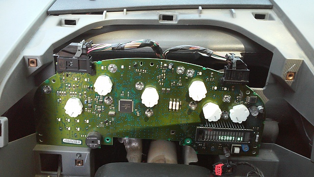
Cluster only in dash:
Testing w/Meter:
LCD screen from left side:
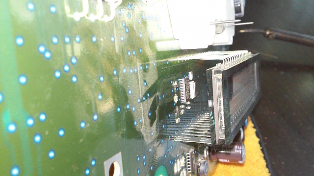
Resistor that was bad (black square with "102" on it) I re-flowed the solder on all 6 of its connections:
I then modified my soldering iron with a file and pliers to get a sharper point and correct angle to get into this tight space. Too much coffee didn't help steady my hand for this task, but I lucked out, and didn't bridge any soldered joints. I didn't add any solder, just tinned the tip and touched each joint to reflow the solder. Re-plugged into the dash and presto, all systems go.
I'm only about 50 miles in after making this repair, but feeling confident for now (knock on wood).
I'm new to the forums as of this post, but I've read many a thread and just wanted to share something that I was having trouble finding myself.
Here's where mine is different from Murf's. Once you get down to the circuit board, the LCD panel is green lighted letters and a black background, and instead of unplugging and cleaning the pins mine has all 40+ pins soldered directly to the board. After I got the needles and screen off I realized this difference and almost packed it up, and started looking for a replacement. A little more searching and I found that a guy with a 2005 Windstar showed off that he had a similar issue with the flickering screen and his fix was a bad resistor solder joint on the circuit board.
Here's my gauge cluster:

I plugged the circuit board back into the dash and as the board flexed the odometer would go on and off. I was able to use a meter and see which pin from the LCD screen was changing voltage during this flicker, and then traced the maze on the circuit board back to the nearest resistor, located under the LCD.
Cluster only in dash:

Testing w/Meter:

LCD screen from left side:

Resistor that was bad (black square with "102" on it) I re-flowed the solder on all 6 of its connections:

I then modified my soldering iron with a file and pliers to get a sharper point and correct angle to get into this tight space. Too much coffee didn't help steady my hand for this task, but I lucked out, and didn't bridge any soldered joints. I didn't add any solder, just tinned the tip and touched each joint to reflow the solder. Re-plugged into the dash and presto, all systems go.

I'm only about 50 miles in after making this repair, but feeling confident for now (knock on wood).
I'm new to the forums as of this post, but I've read many a thread and just wanted to share something that I was having trouble finding myself.
06-22-2015, 07:41 AM
#69
Member

Great job! More guts and patience than I have. After two years, mine all of a sudden came on. I know it probably won't last but it has been two months and I'm enjoying it while it lasts.
So I've done much research on this, and I haven't found anything particular to my situation. I have 2007 F150 Lariat and the cluster is slightly different. I'd first like to thank murf for the great writeup, because I would have stopped at checking the back for bad solder joints and never took the needles and screen off. His help got me past that part, which is kinda scary in itself.
Here's where mine is different from Murf's. Once you get down to the circuit board, the LCD panel is green lighted letters and a black background, and instead of unplugging and cleaning the pins mine has all 40+ pins soldered directly to the board. After I got the needles and screen off I realized this difference and almost packed it up, and started looking for a replacement. A little more searching and I found that a guy with a 2005 Windstar showed off that he had a similar issue with the flickering screen and his fix was a bad resistor solder joint on the circuit board.
Here's my gauge cluster:
Attachment 385619
I plugged the circuit board back into the dash and as the board flexed the odometer would go on and off. I was able to use a meter and see which pin from the LCD screen was changing voltage during this flicker, and then traced the maze on the circuit board back to the nearest resistor, located under the LCD.
Cluster only in dash:
Attachment 385620
Testing w/Meter:
Attachment 385624
LCD screen from left side:
Attachment 385622
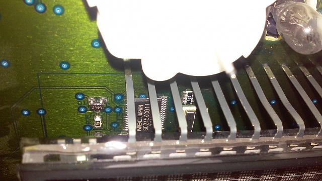
Resistor that was bad (black square with "102" on it) I re-flowed the solder on all 6 of its connections:
Attachment 385623
I then modified my soldering iron with a file and pliers to get a sharper point and correct angle to get into this tight space. Too much coffee didn't help steady my hand for this task, but I lucked out, and didn't bridge any soldered joints. I didn't add any solder, just tinned the tip and touched each joint to reflow the solder. Re-plugged into the dash and presto, all systems go.
Attachment 385621
I'm only about 50 miles in after making this repair, but feeling confident for now (knock on wood).
I'm new to the forums as of this post, but I've read many a thread and just wanted to share something that I was having trouble finding myself.
Here's where mine is different from Murf's. Once you get down to the circuit board, the LCD panel is green lighted letters and a black background, and instead of unplugging and cleaning the pins mine has all 40+ pins soldered directly to the board. After I got the needles and screen off I realized this difference and almost packed it up, and started looking for a replacement. A little more searching and I found that a guy with a 2005 Windstar showed off that he had a similar issue with the flickering screen and his fix was a bad resistor solder joint on the circuit board.
Here's my gauge cluster:
Attachment 385619
I plugged the circuit board back into the dash and as the board flexed the odometer would go on and off. I was able to use a meter and see which pin from the LCD screen was changing voltage during this flicker, and then traced the maze on the circuit board back to the nearest resistor, located under the LCD.
Cluster only in dash:
Attachment 385620
Testing w/Meter:
Attachment 385624
LCD screen from left side:
Attachment 385622
Resistor that was bad (black square with "102" on it) I re-flowed the solder on all 6 of its connections:
Attachment 385623
I then modified my soldering iron with a file and pliers to get a sharper point and correct angle to get into this tight space. Too much coffee didn't help steady my hand for this task, but I lucked out, and didn't bridge any soldered joints. I didn't add any solder, just tinned the tip and touched each joint to reflow the solder. Re-plugged into the dash and presto, all systems go.
Attachment 385621
I'm only about 50 miles in after making this repair, but feeling confident for now (knock on wood).
I'm new to the forums as of this post, but I've read many a thread and just wanted to share something that I was having trouble finding myself.
04-11-2016, 09:50 AM
#70
Junior Member

Join Date: Apr 2016
Posts: 1
Likes: 0
Received 0 Likes
on
0 Posts
First time posting here. To the OP, thanks much for your post.
After seeing a couple of posts about cold solder joints I went ahead and removed my cluster last night. First thing I noticed was there were no cold solder joints, the LCD plugged into a socket - not connected via some small ribbon cable that I was anticipating from the other posts Second thing I noticed was the pins were not in the socket. Might have disloged while taking it apart, not sure. I did not take to whole black faceplate off, just carefully pulled up in the corner and reinserted the LCD.
In any case, I was not able to make the LCD work, yet. Will give it a go when I have some daylight to work in.
[MENTION=95445]wakeboardnmoto[/MENTION]:
Same symptoms with the door lock/LCD here, so it may be some other area (computer, not LCD), I don't know. Also, there was a post in this thread that mentioned an issue with the trailer light ground, that somehow fixed the LCD.
In regard to the small cable coming out of the bottom, that is PRNDL and can be removed from the cluster housing by depressing a small clip on each side and sliding it down.
After seeing a couple of posts about cold solder joints I went ahead and removed my cluster last night. First thing I noticed was there were no cold solder joints, the LCD plugged into a socket - not connected via some small ribbon cable that I was anticipating from the other posts
Second thing I noticed was the pins were not in the socket. Might have disloged while taking it apart, not sure. I did not take to whole black faceplate off, just carefully pulled up in the corner and reinserted the LCD. In any case, I was not able to make the LCD work, yet. Will give it a go when I have some daylight to work in.
[MENTION=95445]wakeboardnmoto[/MENTION]:
Same symptoms with the door lock/LCD here, so it may be some other area (computer, not LCD), I don't know. Also, there was a post in this thread that mentioned an issue with the trailer light ground, that somehow fixed the LCD.
In regard to the small cable coming out of the bottom, that is PRNDL and can be removed from the cluster housing by depressing a small clip on each side and sliding it down.
I just bought my truck and it was flashing barely. I pulled it out to check the joints to discover that the guy had already sent my cluster to AutoEcu twice to have it fixed. It was done right before he sold the truck (lucky me).
My truck too locks the doors after coming to random stop sand accelerating. So it must be due to inconsistent grounding.
I tore it apart once and had no luck getting it to work. I tore it apart again yesterday and put as much electrical grease inside of the LCD pin block on the cluster board as I could. I put it back together and it seems to be working. It does make much sense to me because I checked the continuity from solder joints to LCD and they were fine but were not working until I added the grease. So if you are unable to get it working, I would suggest reflowing solder on the pins on the bottom and then putting as much grease in the block as possible.