
Stereo Build in 2013 Ford F150 FX4
 03-06-2014, 10:47 AM
#31
Boost :)

@ TJPlatinumEB, I must have run past your post too quickly. I guess for some reason, I didn't comprehend what you were saying. I was so caught up on locating a wire behind the head unit/navigation. I checked out my manual and Fuse 38 is perfect. I just wish I would have recognized your post the first time I saw it. Another great part is the fact that it falls right into the electrical tray on the passenger side of the vehicle. I can run it straight back.
Here's a question though, how can I determine how many amps I'll be drawing from the 3 devices attached? The three devices include 2 amps) Sound Qubed Q1200x1, A 4-channel amp (Not sure what yet) that has 400 watts rms, and I'm thinking Audio Control LC8I.
I thought I ran into a snag and learned all about relays. I now understand how to wire/install a SPDT Relay, and now I don't even have to do it. I wanna show off my newly acquired skills!! lol
As far as current draw on it, there should be next to zero. The amp(s) aren't pulling anything off of this wire other than if there is a signal there or not. It just acts as an on/off switch. In my previous 2011 truck I ran two amps and a large sound processor off of the same individual remote wire from the kick panel. Just daisy chained them together running from one to the other. Zero issues. Been doing that in vehicles for the past 15 years and doing stereo installs. Not a single problem doing it this way.
Think of the amp like just a big relay if you want to and if it makes more sense. It has a constant 12v from the battery, grounded as well, and just needs that signal to tell it when to start pulling on that 12v from the battery to supply power to it to power the sub or speakers it is driving. The current draw is on the battery, not the remote wire.

The following users liked this post:
jr07 (03-07-2014)
03-07-2014, 12:57 AM
#32

Ok, so with about 3 more hours of research here are some questions that have come up regarding the installation:
1. The factory amp is in the center console. I'd have to tap into the amp wiring in order to create an RCA signal to both amps to tie to Head Unit/Nav. Is this correct? If so, do you tie into the wires leading into the amp or coming out?
I found this wiring schematic for the speakers for pre 2013 trucks; Is this accurate? This would be considered wires leading out the amp...not in.
Center Front Speaker on Dash (+) Green, (-) Gray/Yellow
Driver Front Speaker (+) White, (-) White/Brown
Driver Front Tweeter (+) Green/Orange, (-) Gray/Orange
Passenger Front Speaker (+) White/Purple, (-) White/Orange
Passenger Front Tweeter (+) Purple/Orange, (-) Yellow/Orange
Driver Rear Door (+) White/Green, (-) Brown/Yellow
Passenger Rear Door (+) Brown/White, (-) Brown/Blue
Sub Dual Voice Coil
1) (+) Purple/Green, (-) Green/White
2) (+) Green/Purple, (-) Gray
*On the Speaker Terminals, the Clip Side is the (+) positive terminal
These are all wires which are run to speakers, so would I even tie into these? My first thought is no. Which wires off the amp would I use in order to create the RCA signals?
All input is appreciated.
03-07-2014, 08:22 AM
#33
for the fuse rating coming from the battery to the Dblock that will power the amps.... easy, remove all the fuses from the amps themselves add up all the ratings, round up, use that for the D block fuse rating. if it does not have a fuse the manual should say its current draw.
as far as before or after the amp it's your call. the LC6i can take either before or after amp signals. I'd probably just take it from before the amp if it was me as you would be getting the full, uncrossed, signal. the LC6i does signal summing so if you hook up the front passenger speaker, front passenger tweeter, and the sub you will have rebuilt the vast majority of the original signal. If you take it before the amp you need to do at most 8 wires if my guess is correct. Also, post the wire diagram for the amp input as well if you found it. I am thinking of redoing my own setup now, even after I was sure I was just gonna leave it alone.
and just to make sure you are following, the signals you are tapping into have to go to the LC6i which will in turn give you the RCA preout.... you can not just tie in RCAs to the speaker wires.
The following users liked this post:
jr07 (03-08-2014)
03-08-2014, 01:02 PM
#34
installing the fuses on the main power (0 gauge) and the alternator power wire (0 gauge) should be no problem at all.
the turn on lead wire will be run from the delayed fuse (#38) on the kick panel with an add a fuse. I'm trying to determine the gauge of the add a fuse wire. it has to be 16-18 gauge. Rather than piggy backing the turn on from each device, I think the route I'm taking is using an in-line butt connector (1 wire in, 3 wires out. it's made by a company NSPA connectors. They are pretty legit.
@ torinalth, so from your last post, if i'm understanding correctly, rca's will only be needed from the amps to the Audio Control module. The Audio Control module will convert the signal back up to the head unit. (No RCA's necessary)
i may open my center console up today;if i'm able to i'll post some detailed pics of the amp and all the wiring to help provide a visual.
The following users liked this post:
Newbie 5 (07-14-2021)
03-08-2014, 02:08 PM
#35
Junior Member

Hey man,
I like the idea of the Cleansweep. I have done quiet a few installs with it and love it. Regardless what you go with you can just run a pair or 12awg from the 12+ and GND to the Cleansweep or Kicker.
Have you thought of a 5 Channel? JL makes the HD900/5 and the XD 700/5 and they save space and delivery amazing quality sound. There are other brands that do the same. Audison makes good ones also.
The following users liked this post:
jr07 (03-08-2014)
03-08-2014, 02:47 PM
#36
Appreciate the post.
Currently, I'm removing my center console. The only thing preventing me from removing the entire thing is the shifter cable. I found a forum on here where it states that it just "pops" off, but did not provide a visual of where he talking about. Need a little help...
It must pop off where it actually attaches to the shifter; Here's some pictures to help provide a visual
03-08-2014, 03:48 PM
#37
Cable that connect to the shifter has been removed. I found that the braces which link hold the shifter to a bracket freed up some space which allowed me to "pop" the very end off.
Now, I'm having trouble with a bracket that keeps the shifter cable stationary. Here are some pics to show everything I'm talking about.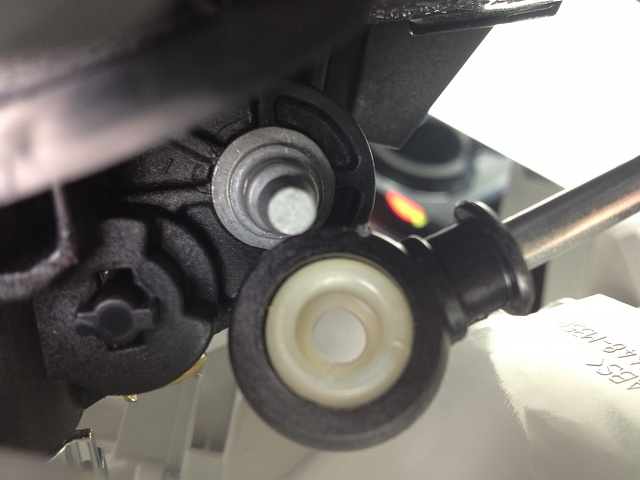
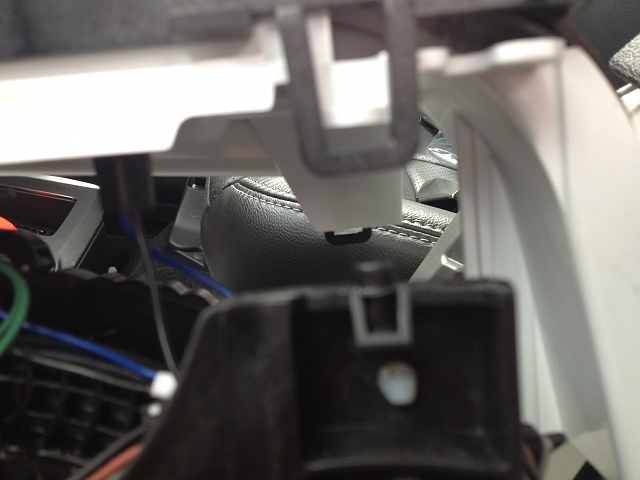
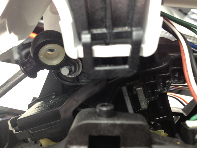
Now, I'm having trouble with a bracket that keeps the shifter cable stationary. Here are some pics to show everything I'm talking about.


 03-09-2014, 01:31 AM
#39
Today was definitely a learning experience. I removed the center console for 2 reasons before I actually start installing:
1. I now understand how to remove the entire console pretty easily. Ran into a few snags , but managed to figure out a simple solution. Here are some of the photos that will hopefully benefit someone else who is trying to do the same thing:
1. I now understand how to remove the entire console pretty easily. Ran into a few snags , but managed to figure out a simple solution. Here are some of the photos that will hopefully benefit someone else who is trying to do the same thing:
03-09-2014, 01:42 AM
#40
The 2nd reason I removed the center console is get some pictures of the wiring that I'm planning on using. I took some pictures of the connectors that plug into the stock sony amp. Here is where I need some help.....which of these plugs/connectors will I need to use? I really don't want to cut into the factory wiring harness so whichever connectors I will need, I'd like to find a matching male end that will connect into the females. If anyone can provide clarity from the photos I attach, I'd really appreciate it!