
Need help installing OEM Power Boards
 02-12-2014, 08:13 AM
#21
noob :)

Here is a ebay link to the part number... the ford diagram is pointing behind the rear seat here too...
Seems ford parts dropped a B off the part number... 9L3Z-14C177-B
http://www.ebay.ca/itm/NEW-OEM-POWER...-/230885511787
Seems ford parts dropped a B off the part number... 9L3Z-14C177-B
http://www.ebay.ca/itm/NEW-OEM-POWER...-/230885511787
Last edited by byte; 02-12-2014 at 08:40 AM.
 02-12-2014, 08:23 AM
#22
Senior Member
Thread Starter


Here is a ebay link to the part number... the ford diagram is pointing behind the rear seat here too...
http://www.ebay.ca/itm/NEW-OEM-POWER...-/230885511787
http://www.ebay.ca/itm/NEW-OEM-POWER...-/230885511787
02-12-2014, 08:45 AM
#23
noob :)
I am just learning the ford parts diagrams so bear with me as well...
on the diagram that shows the back of the cab, the C3313A and B are CONNECTORS... I was thinking there was two modules behind the seat! They are showing the two plugs on the wiring harness, not the module. And your module looked like it had two plugs going into it
 02-12-2014, 08:57 AM
#24
Senior Member
Thread Starter
I am just learning the ford parts diagrams so bear with me as well...
on the diagram that shows the back of the cab, the C3313A and B are CONNECTORS... I was thinking there was two modules behind the seat! They are showing the two plugs on the wiring harness, not the module. And your module looked like it had two plugs going into it
on the diagram that shows the back of the cab, the C3313A and B are CONNECTORS... I was thinking there was two modules behind the seat! They are showing the two plugs on the wiring harness, not the module. And your module looked like it had two plugs going into it
Yes your right they are connectors. See if have the wiring harness and it all looks like interior wiring. That would explain it being inside the cab. Guess I'll find out later today, let's hope. Thanks for your help.
02-12-2014, 07:49 PM
#26
Senior Member
Thread Starter
Ok let's go through this wiring harness that I have.
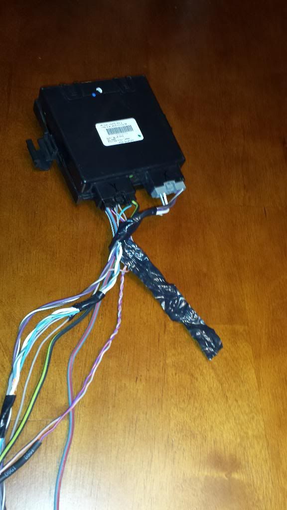
The module with the connectors from the harness in.
The ground and hot wire.
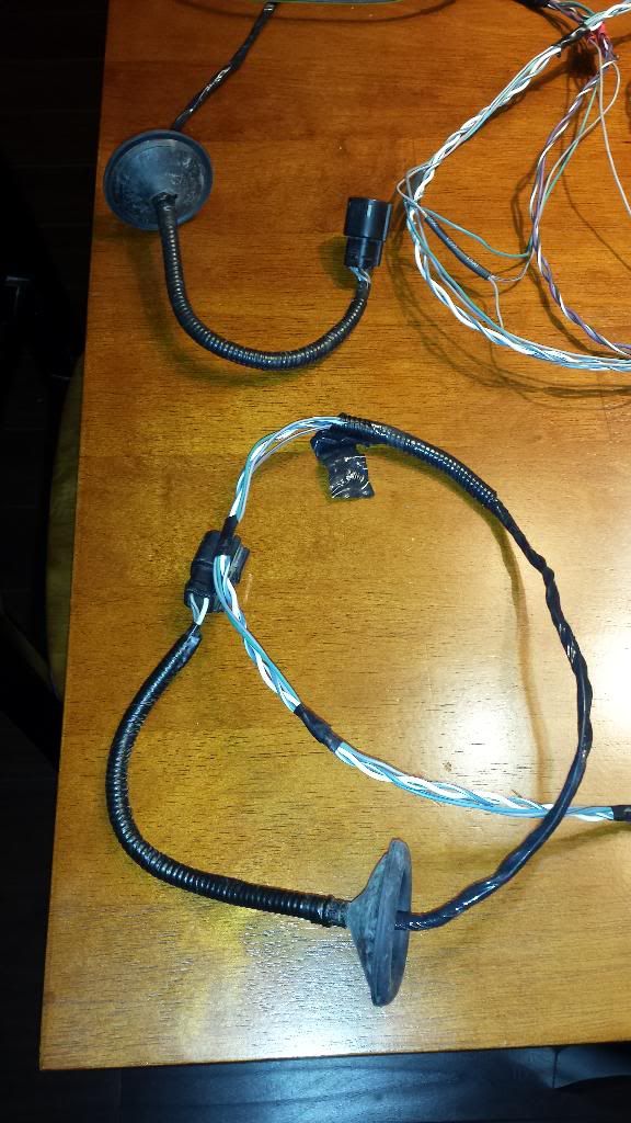
The connectors that go to the motors on the running boards.
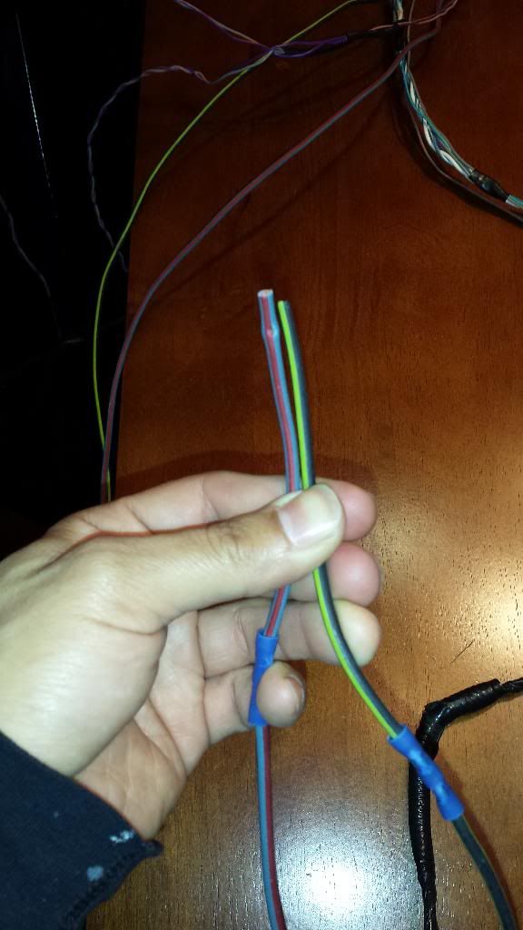
Now there's these 2 wires. A orange/violet and a orange/gray wire. From the diagram it says they go to the network communication module. I have no clue where that is or where to tie these in.

The module with the connectors from the harness in.

The ground and hot wire.

The connectors that go to the motors on the running boards.

Now there's these 2 wires. A orange/violet and a orange/gray wire. From the diagram it says they go to the network communication module. I have no clue where that is or where to tie these in.
02-13-2014, 12:09 AM
#27
noob :)
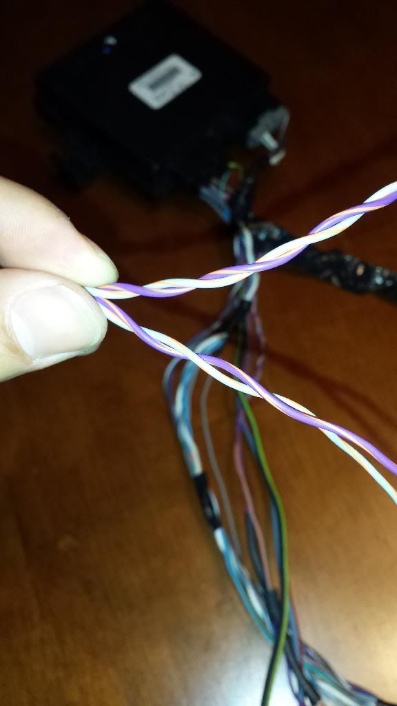
Here is where they point the twisted pair set to...

The following users liked this post:
vtoy1 (04-26-2017)
02-13-2014, 12:12 AM
#28
noob :)
I would say hang the module behind the seat then lay the wires out to see where about they would reach to... from the power and negative wires I see a non factory connector on there... almost like someone all ready put this set on a truck after factory... does the seller have more info for you?
02-13-2014, 12:16 AM
#29
noob :)
The bcm (body control module) is under the passenger kick panel which will have the power and twisted data wire there...
02-13-2014, 12:45 AM
#30
Op, I know you really want this to be an oem clean, install. But would it be easier to possibly call Amp, and see if you could rig it up using the aftermarket method? Chances are you may lose the function to cancel the operation or control it from the cluster like the OEM. But at least you could still get them working, probably just need to get an aftermarket harness from Amp?
Just thinking out loud. I'm subscribing, as I really am pulling for you to figure out an OEM solution, as I would really like to do this mod to my FX4. I hate the 2013, FX4 running boards with a passion. But I use them daily.
Just thinking out loud. I'm subscribing, as I really am pulling for you to figure out an OEM solution, as I would really like to do this mod to my FX4. I hate the 2013, FX4 running boards with a passion. But I use them daily.