
Help with upfitter pigtail wiring please!!!
 01-19-2013, 01:26 PM
#1


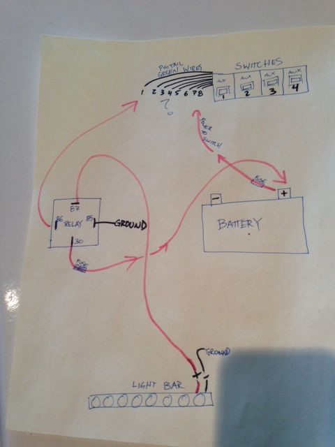
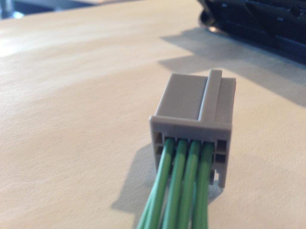
Im having trouble searching for any thread with the wiring on the Raptor upfitter pigtail wires. I swaped the console into my ecoboost and need to wire a 20" lightbar up. I have the upfitter switches and pigtail, but theres 8 green wires off the back. I need to know if anyone has the pigtail wire names. They do read left to right, top - 1,2,3,4, bottom- 5-6-7-8. Now are they just Positive and aux wires no ground?? because all the relay wiring diagrams show the switch having power, ground,auxilary, so do these switches have no ground and just use the relay ground?
Edit: So far i assume each switch does NOT use a ground, although maybe 1 single wire is. I just need to find a diagram of the harness wires and i cant find anywhere. So far this is what i have discovered testing wires together. Im running 1 wire to aftermarket relay, and 1 wire directly from battery both inline fused...
When i cross...
-wires 1 & 8 let switch 4 illuminate lightbar
-wires 6 & 8 let switch 2 illuminate lightbar
-wires 7 & 8 let switch 1 illuminate lightbar
-wires 3 & 7 light up switch #1 amber(only w/const power to wire 7)
-wires 3 & 6 light up switch #2 amber(only w/const power to wire 6)
-wires 3 & 5 light up switch #3 amber(only w/const power to wire 5)
-wires 6 & 1 light up switch #4 amber on if switches 2 & 4 are flip on
-wires 3 & 2 light up the blue "AUX" words(only w/const pwr to wire 2)
-wire 4 does nothing?????
Please help me figure out the pattern!!!!
 Ill try to load pics but photobucket is all different so im trying to work it out
Edit: So far i assume each switch does NOT use a ground, although maybe 1 single wire is. I just need to find a diagram of the harness wires and i cant find anywhere. So far this is what i have discovered testing wires together. Im running 1 wire to aftermarket relay, and 1 wire directly from battery both inline fused...
When i cross...
-wires 1 & 8 let switch 4 illuminate lightbar
-wires 6 & 8 let switch 2 illuminate lightbar
-wires 7 & 8 let switch 1 illuminate lightbar
-wires 3 & 7 light up switch #1 amber(only w/const power to wire 7)
-wires 3 & 6 light up switch #2 amber(only w/const power to wire 6)
-wires 3 & 5 light up switch #3 amber(only w/const power to wire 5)
-wires 6 & 1 light up switch #4 amber on if switches 2 & 4 are flip on
-wires 3 & 2 light up the blue "AUX" words(only w/const pwr to wire 2)
-wire 4 does nothing?????
Please help me figure out the pattern!!!!
Ill try to load pics but photobucket is all different so im trying to work it out
Last edited by Leadsled124; 01-19-2013 at 04:55 PM.
 01-20-2013, 08:49 PM
#3
No reply's????? Shoulda made the title "boobies"
Anyways. Need wiring expert please!!!! Got my lightbar hooked up and working off switch 1, need to illuminate the buttons and "AUX" letters do I can see the buttons at night
Anyways. Need wiring expert please!!!! Got my lightbar hooked up and working off switch 1, need to illuminate the buttons and "AUX" letters do I can see the buttons at night

The following 2 users liked this post by raceman:
Gibby1234 (05-15-2014),
Leadsled124 (03-02-2013)
03-08-2013, 02:57 PM
#6
Take a look at this https://www.fleet.ford.com/truckbbas...ml/Q-117R2.pdf
Ok i saved that link but superdutys have the wires under the steering wheel not the passenger kick panel (ex: f150 raptor). I had everything working, well just running 2 offroad lights for switches 1 &2, just no interior switch illumination.
I know have another piece of the puzzle which is the "relay harness" part number #BC32-14A303-B
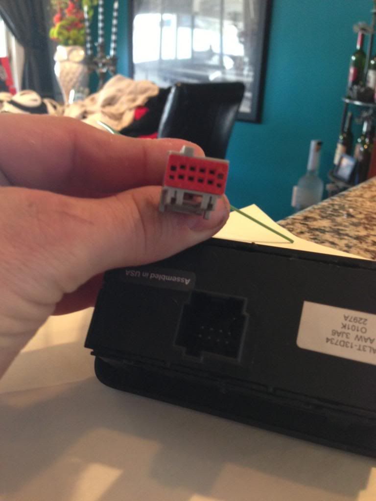
^^ This should delete the pigtail 8 wire green harness. It has the 4 blunt wires like the superduty and raptor to accept the switch wires. Piece of cake. Now my only issue is i CAN NOT find where the plug or the BCM is. The BCM should have another female larger 8 pin adaptor somewhere by the passenger kick plate??? please help all the instructions online are for raptors and superdutys.
03-08-2013, 03:54 PM
#7

So, the upfitter assembly comes with enclosure, switches and relay with factory connectors?
Why not just use the assembly just for the switches?
Bypass the factory relay, power and connector? Run your own switch wire(s) to a new relay(s) mounted under the dash or hood?
Why not just use the assembly just for the switches?
Bypass the factory relay, power and connector? Run your own switch wire(s) to a new relay(s) mounted under the dash or hood?
Trending Topics
03-08-2013, 05:28 PM
#8
So, the upfitter assembly comes with enclosure, switches and relay with factory connectors?
Why not just use the assembly just for the switches?
Bypass the factory relay, power and connector? Run your own switch wire(s) to a new relay(s) mounted under the dash or hood?
Why not just use the assembly just for the switches?
Bypass the factory relay, power and connector? Run your own switch wire(s) to a new relay(s) mounted under the dash or hood?
03-08-2013, 05:41 PM
#9
Senior Member
So, the upfitter assembly comes with enclosure, switches and relay with factory connectors?
Why not just use the assembly just for the switches?
Bypass the factory relay, power and connector? Run your own switch wire(s) to a new relay(s) mounted under the dash or hood?
Why not just use the assembly just for the switches?
Bypass the factory relay, power and connector? Run your own switch wire(s) to a new relay(s) mounted under the dash or hood?
Based on the pinout, pin #2 is the illumination sense while pin 8 should be a hot-fused 10A circuit. The LEDs are grounded through pin 3.
As for the BCM plug, I don't think the trucks (other than Raptor and SD) have it. Or at least the 2010s didn't have it, which is why I abandoned the project (all of this based on lots of exploring and the Haynes manual). Theoretically with the relay harness, you could just chop off the connector and deal with the wires directly based on the pinout in the wiring diagrams.
Also, for some reason there are fuse holder in the relay box, but they don't have contacts in them, so the hot lines need to be fused outside the relay box. I was looking into some some small project car fuse boxes, but never got around to it.
This is my goto reference for everything on our trucks (besides Haynes): https://www.fleet.ford.com/truckbbas...3/maintoc.html
Last edited by steenbag; 03-08-2013 at 06:01 PM. Reason: Typos...
The following users liked this post:
Leadsled124 (03-08-2013)
03-08-2013, 06:50 PM
#10
I looked into doing this a while back, in fact I had bought all of the parts and laid out a schematic (can't find it now unfortunately). The cleanest way I found to do it was to buy PN 9C3Z-14A303-A (the part # you listed may be similar, I couldn't find it). This is the power module that you can see in the top left corner of Fig 1 in the previously linked PDF. The box contains all of the relays, the ground strap, the 4 "blunt cut wires" and the connector that goes to the upfitter switch assembly.
Based on the pinout, pin #2 is the illumination sense while pin 8 should be a hot-fused 10A circuit. The LEDs are grounded through pin 3.
As for the BCM plug, I don't think the trucks (other than Raptor and SD) have it. Or at least the 2010s didn't have it, which is why I abandoned the project (all of this based on lots of exploring and the Haynes manual). Theoretically with the relay harness, you could just chop off the connector and deal with the wires directly based on the pinout in the wiring diagrams.
Also, for some reason there are fuse holder in the relay box, but they don't have contacts in them, so the hot lines need to be fused outside the relay box. I was looking into some some small project car fuse boxes, but never got around to it.
This is my goto reference for everything on our trucks (besides Haynes): https://www.fleet.ford.com/truckbbas...3/maintoc.html
Right now i have...
-Pigtail wire 7 to relay
" wire 8 to constant power fused (so i ccan use when truck off)
This powers switch 1
-Pigtail wire 6 to relay
" wire 8 to constant power (but that wire is already wired on step 1)
This powers switch 2