
Reverse monitor/4.2" relocate teaser
 02-07-2014, 07:22 PM
#1
Member

Thread Starter


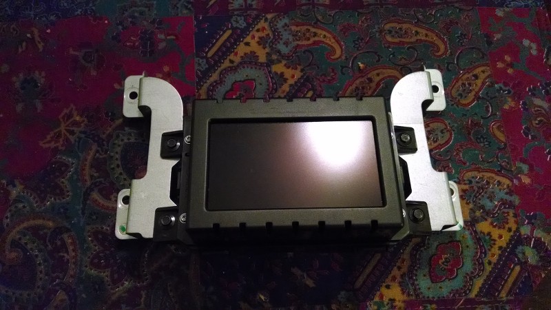
Just as the title suggests I am currently taking on the task of relocating the back up monitor from the tiny mirror screen down to the 4.2" screen center dash, I have so far passed several hurdles and thought I would pass along what I have found so far.
After reviewing wiring diagrams for the 2013 non touch my Ford with sync and 4.2" screen as well as the wiring diagram for the 2014 Ford Escape (wife's truck) that inspired me to attempt this mod because she has the same 4.2" screen and that's where her reverse cam lights up, as well as a 2014 F150 that comes with that same screen and they put the reverse monitor there probably after hearing so many of us bitch about it LOL.
Any way all 3 vehicles use the EXACT same center screen (part# identical) so that's one hurdle, another was to dissect the connector to move pins around because we have to move the power wire from pin 12 to pin 1 as per the diagrams, well that was an epic fail, I tried everything I knew and no dice, these micro connectors are built to never come apart with out destroying it. arggg
On the table for a more comfortable examination...
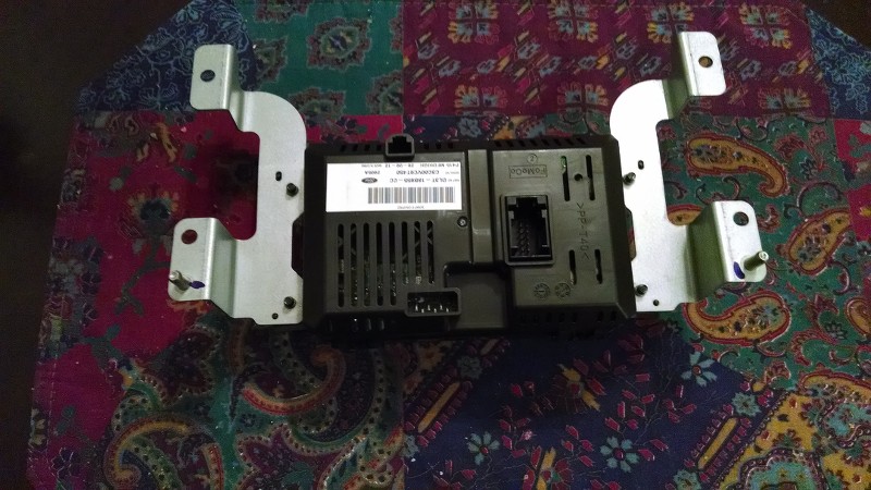
So I do a little more digging and found what I thought would make an acceptable replacement connector for the stock one and hit PAY DIRT!!
As seen below the 1st pic shows the locking tab forward in the unlocked position and the 2nd pic is the connector locked on to the screen snug as a bug made for each other.

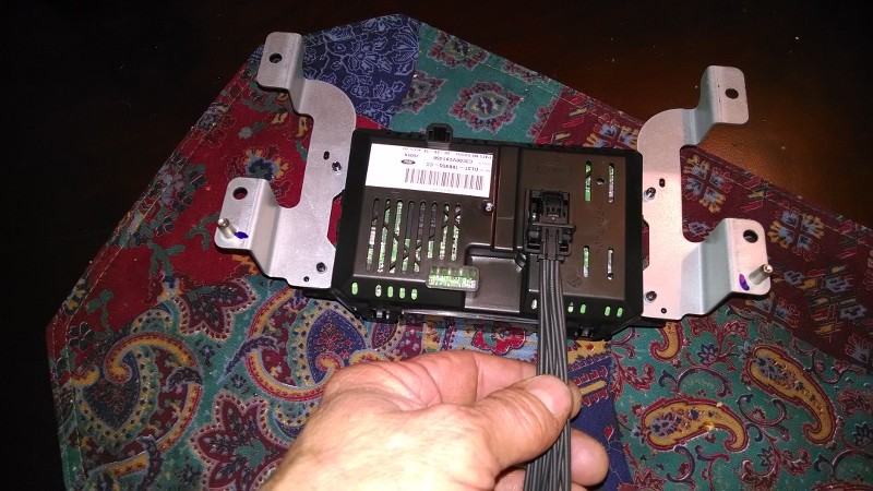
Since I already have my dash mostly in the back seat, i'm going to continue tomorrow with identifying pins with wires because as you can see the replacement connector wiring is not color coded which shouldn't be a problem for anyone that knows how to check continuity with a dvom, the main thing is finding the pin 1 wire and the rest should fall right into place for splicing.
So any way I'm too deep into this mod to give up now and I'm almost 99.99% sure this will work but I'll find out some time this weekend and follow up with either me sitting with a smoked 4.2" screen and or doing the happy dance
Stay tuned.
.
After reviewing wiring diagrams for the 2013 non touch my Ford with sync and 4.2" screen as well as the wiring diagram for the 2014 Ford Escape (wife's truck) that inspired me to attempt this mod because she has the same 4.2" screen and that's where her reverse cam lights up, as well as a 2014 F150 that comes with that same screen and they put the reverse monitor there probably after hearing so many of us bitch about it LOL.
Any way all 3 vehicles use the EXACT same center screen (part# identical) so that's one hurdle, another was to dissect the connector to move pins around because we have to move the power wire from pin 12 to pin 1 as per the diagrams, well that was an epic fail, I tried everything I knew and no dice, these micro connectors are built to never come apart with out destroying it. arggg
On the table for a more comfortable examination...
So I do a little more digging and found what I thought would make an acceptable replacement connector for the stock one and hit PAY DIRT!!
As seen below the 1st pic shows the locking tab forward in the unlocked position and the 2nd pic is the connector locked on to the screen snug as a bug made for each other.
Since I already have my dash mostly in the back seat, i'm going to continue tomorrow with identifying pins with wires because as you can see the replacement connector wiring is not color coded which shouldn't be a problem for anyone that knows how to check continuity with a dvom, the main thing is finding the pin 1 wire and the rest should fall right into place for splicing.
So any way I'm too deep into this mod to give up now and I'm almost 99.99% sure this will work but I'll find out some time this weekend and follow up with either me sitting with a smoked 4.2" screen and
or doing the happy dance Stay tuned.
.
Last edited by RLXXI; 02-07-2014 at 09:51 PM. Reason: clarity

The following users liked this post:
Wanted33 (02-11-2014)
02-07-2014, 07:45 PM
#2
Senior Member

Instead of trying to remove the pin from the connector housing you could cut the wires for pin one and twelve and solder the wire from pin one to the wire from pin twelve and vise versa.
02-07-2014, 07:49 PM
#3
Member
Thread Starter
02-07-2014, 08:33 PM
#5
Member
Thread Starter
You would have to look at it up close to understand there is no room at all, the only other time I've seen connectors with pins so small was a computer mother board. Trust me I have been researching this from every angle and the only solution is the replacement connector, fortunately it has all 12 wires. Not all will be used.
.
The following users liked this post:
scole (02-07-2014)
02-10-2014, 06:24 PM
#6
Member
Thread Starter
Ok well I identified all the wires by pin # on the replacement harness/connector and was just about to start splicing but for what ever reasons of anxiety either imagined or founded, I just can't cut into the factory harness. 
With that said I can send to anyone brave enough to make this mod happen all supporting documentation. Should you decide to take it on, I am not responsible if you zap your electrical system. Send a PM for info.
This post will self destruct in ..........
.
With that said I can send to anyone brave enough to make this mod happen all supporting documentation. Should you decide to take it on, I am not responsible if you zap your electrical system. Send a PM for info.
This post will self destruct in ..........
.
02-10-2014, 06:37 PM
#7
Senior Member
oh...lol.... thats sweet...guess i'll have to look at the connector and see for myself. once i look i'll check our suppliers for pins....
thanks for taking the time for us..
thanks for taking the time for us..
Trending Topics
02-10-2014, 06:49 PM
#8
Member
Thread Starter
This is the connector required.

Basically all that needs to be done is move the power wire from pin 12 to pin 1, pins 6 and 12 are the video + and - respectively that need to be taken from the mirror, it's shielded so my thoughts were to cut the harness on the drivers side harness run under the sill plate back far enough to route up thru the dash to the 4" display.
Pm if you want the other docs.
.
Last edited by RLXXI; 02-10-2014 at 07:10 PM.
The following users liked this post:
lucas8888 (04-06-2016)
02-10-2014, 07:12 PM
#10
Member
Thread Starter

The following users liked this post:
Steve Osborne (02-10-2014)