Retrofit 2017 F-250 Aux Switch Panel in F-150
#171
Senior Member
So the harness you bought was the whole console harness and you cut off the connector that went to the switches so you make your own? Would be much clearer if you had any pics of the wiring you did. Any chance you can post those?
#172
Senior Member
iTrader: (3)
The console is installed already and wired the onlybthing i hvae to do still is wire the relay box. Asfar as witing its simple for the console one ground 1 illumination wire for yhe switches 2 power sources for the switches and then 6 signal wires to relays i will post the pinout for the upfitter connector
#174
Senior Member
2015 xlt and I did it all super easy took 4 hours and that was me taking my time making the harness and all this is the console and harness I used and it all was 160 and change shipped to my door. Fairway ford in Ohio hooked me up and helped me out Kevin is the parts guy there!
Where did you get the fuse/relay box?
#175
Senior Member
iTrader: (3)
Originally Posted by Jim10517
I'm assuming that you had to move components from your original console to the new one. Correct?Where did you get the fuse/relay box?
Great product price and quality !! Worth every penny!
The following users liked this post:
shadowblackscrew (08-22-2020)
#176
Junior Member

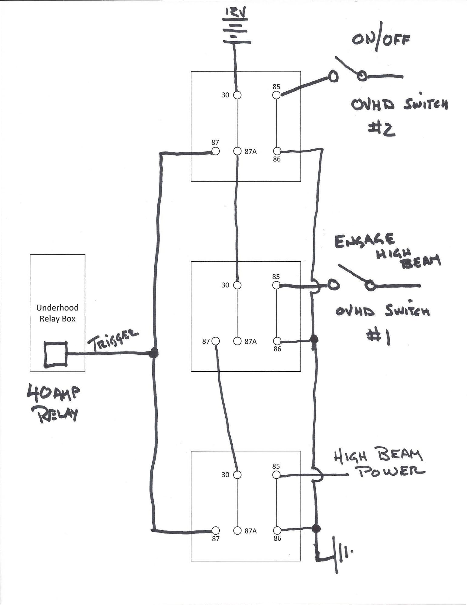
I am now doing the wiring diagram, Here is what I came up with to feed the Upfitter Relay box under the hood. I want to be able to run my Moose Lights either by simple on/off OR triggered by High Beams. I came up with a 3 relay drawing, not being an electrical guru.... is this correct and/or can it be done simpler/fewer relays???
#177
Senior Member
Originally Posted by jerehawn
I am now doing the wiring diagram, Here is what I came up with to feed the Upfitter Relay box under the hood. I want to be able to run my Moose Lights either by simple on/off OR triggered by High Beams. I came up with a 3 relay drawing, not being an electrical guru.... is this correct and/or can it be done simpler/fewer relays???
There is a way for you to use only one relay, but it will require a FET and some diodes as well. I'm not sure if it would be any simpler for you. I can draw it up if you would like.
#178
Senior Member
deleted
Last edited by bhamilton; 01-21-2017 at 07:20 PM.
#179
Senior Member
I have looked over your drawing and the theory looks good. Are you planning on using this with the OEM up-fitter relay box? I would recommend you put a fuse as close to the 12v positive as you can, that way if a relay develops a fault your less likely to get a fire. I would also recommend you use a diode from whatever you tap off the headlights. It reduces the risk of putting unwanted energy back into the car system.
There is a way for you to use only one relay, but it will require a FET and some diodes as well. I'm not sure if it would be any simpler for you. I can draw it up if you would like.
There is a way for you to use only one relay, but it will require a FET and some diodes as well. I'm not sure if it would be any simpler for you. I can draw it up if you would like.
#180
I think 2 relays will work for this (and a few diodes)...lemme work that up.
Question for jerehawn. The upfitters have 2 power supplies...5,6 can be run hot all the time or ignition power. 1-4 usually wired to ignition power source.
If you want to turn your moose lights on when without key on, i assume you want to use 5 or 6. of course, no rules say you can't run them all on constant power....the makers of interstate batteries will love you when you leave your stuff on overnight!


