Engine turns no fuel pump noise
 01-07-2009, 09:02 PM
#11
Junior Member

Join Date: Jan 2009
Posts: 14
Likes: 0
Received 0 Likes
on
0 Posts
I have a Hanes and a Chilton manuel neither have a three wire inertia switch.
 01-08-2009, 10:15 AM
#13
Junior Member
Thread Starter

Join Date: Jan 2009
Posts: 19
Likes: 0
Received 0 Likes
on
0 Posts
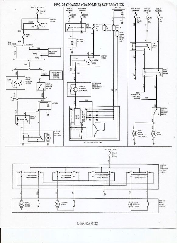
Did find a one schematic, not of complete fuel system but it helps with the puzzle. Found some more in the Van section, will keep looking. Thanks! Good thing I have more time then money
Last edited by USMCord1; 01-08-2009 at 11:21 AM. Reason: found another schematic
01-08-2009, 10:29 AM
#14
Junior Member
Join Date: Jan 2009
Posts: 14
Likes: 0
Received 0 Likes
on
0 Posts
http://i147.photobucket.com/albums/r...ckfuelpump.jpg
Well David this is more confusing now this diagram is from alldata they only show the 2 tank system. Only way to get to the bottom of this is to unplug the connector at the tank and see if you get the 2 second prime with key on and power while cranking. The relay sends power to the inertia fuel shutoff thru the Dark Green/Yellow wire. So if the Red/Yellow wire has the 2 second prime with the key on and while cranking it is purdy safe to say the pump is getting power we have ruled out everything else, for a wiring problem between the inertia switch and the pump, or a ground problem. DO NOT pull the tank. If I remember correctly the pump can be removed by loosening the straps. If you take the pump out you can disconnect the fuel pump wiring and test power and ground at the conector with a test light. This will tell us if the pump is getting a good ground and the battery voltage it needs to operate.
Well David this is more confusing now this diagram is from alldata they only show the 2 tank system. Only way to get to the bottom of this is to unplug the connector at the tank and see if you get the 2 second prime with key on and power while cranking. The relay sends power to the inertia fuel shutoff thru the Dark Green/Yellow wire. So if the Red/Yellow wire has the 2 second prime with the key on and while cranking it is purdy safe to say the pump is getting power we have ruled out everything else, for a wiring problem between the inertia switch and the pump, or a ground problem. DO NOT pull the tank. If I remember correctly the pump can be removed by loosening the straps. If you take the pump out you can disconnect the fuel pump wiring and test power and ground at the conector with a test light. This will tell us if the pump is getting a good ground and the battery voltage it needs to operate.
 01-08-2009, 11:28 PM
#16
Junior Member
Join Date: Jan 2009
Posts: 14
Likes: 0
Received 0 Likes
on
0 Posts
Ok pin
1 is Black/white far right this is fuel pump ground
2 is Yellow/white 2nd from left this is sender positive
3 is PINK/BLACK 3RD from left this is fuel pump power
4 is Orange far left this is sender negitive
It is hard to look at this stuff on the computer. :roll::
1 is Black/white far right this is fuel pump ground
2 is Yellow/white 2nd from left this is sender positive
3 is PINK/BLACK 3RD from left this is fuel pump power
4 is Orange far left this is sender negitive
It is hard to look at this stuff on the computer. :roll::
01-09-2009, 02:00 PM
#17
Junior Member
Thread Starter
Join Date: Jan 2009
Posts: 19
Likes: 0
Received 0 Likes
on
0 Posts
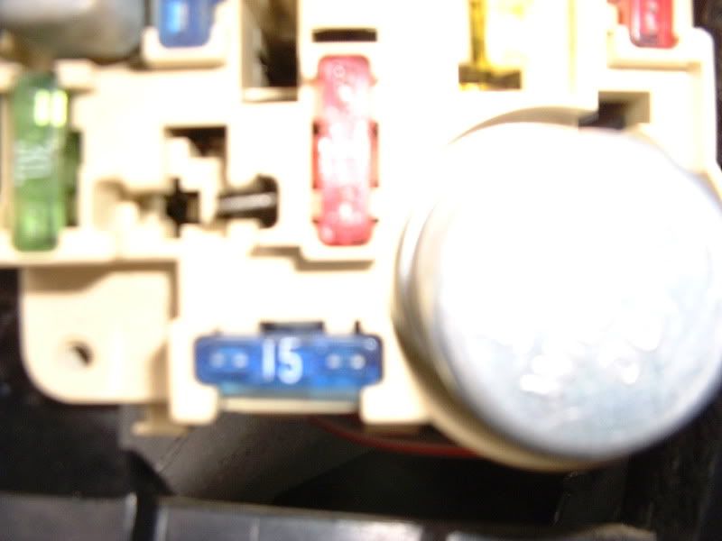
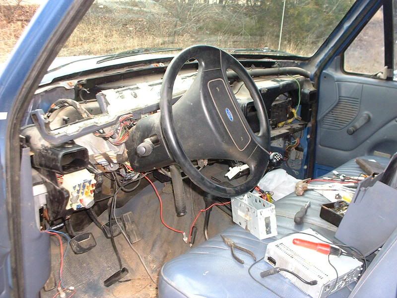
So, I figured I would start from where the problem started. The spade bit where the wire was connected to is dead, was alive before the wire sparked so that is where I am going to start. I took the dash off to better see what is under there, no real big help but the wire coming out of is a orange blk going to hole 70 on the big bundle that does go to the ECU under the hood. Now to find out where that wire goes to. The wire was connected to the spade above the 15 amp fuse and to the left of the red one. Just in case somebody already knows where it goes.
Here is a pic of what it looks like without dash in.
Here is a pic of what it looks like without dash in.
 01-09-2009, 07:23 PM
#19
Senior Member
The only bk/org lines that I can see in my diagrams are either for daytime running lights, auto tranny control, or a fusible link off the positive battery post. I don't have any info about pin 70 to tell for sure what that pin leads to.
Not sure if those ideas will help or not, but might be a couple of places to look.
Not sure if those ideas will help or not, but might be a couple of places to look.
01-09-2009, 08:29 PM
#20
Junior Member
Thread Starter
Join Date: Jan 2009
Posts: 19
Likes: 0
Received 0 Likes
on
0 Posts
Here is what I have got so far David58 and I have been on the phone ALOT (thanks David) but the spade connector (pind #70) that was zapped is now dead . At the fuel shutoff I have momentary power or full power when turning over at the G/Y wire tried jumping from G/Y to R/Y on fuel shut off does nothing to pump. Still have no idea what G/O wire at fuel shutoff does.
Applied power and ground to fuel pump and it runs.
The only fuseable link I have found is by the starter solenoid and it is good.
IF there is power at the inertia fuel shut off (Momentarily) then the fuse and relays for the fuel pump are good, yes?
What am I missing? Are there more fusible links, this is heck without a descent schematic.
I appreciate all suggestions, ideas and or comments.
. At the fuel shutoff I have momentary power or full power when turning over at the G/Y wire tried jumping from G/Y to R/Y on fuel shut off does nothing to pump. Still have no idea what G/O wire at fuel shutoff does. Applied power and ground to fuel pump and it runs.
The only fuseable link I have found is by the starter solenoid and it is good.
IF there is power at the inertia fuel shut off (Momentarily) then the fuse and relays for the fuel pump are good, yes?
What am I missing? Are there more fusible links, this is heck without a descent schematic.
I appreciate all suggestions, ideas and or comments.
Last edited by USMCord1; 01-09-2009 at 08:30 PM. Reason: added comment